


1 - Key P
: This is used to access the programming parameters and
to confirm selection.
2 - Key DOWN
: This is used to decrease the values to be set and to
select the parameters. If the key is held down, the user returns to the
previous programming level until he exits the programming mode.
3 - Key UP
: This is used to increase the values to be set and to
select the parameters. If the key is held down, the user returns to
the previous programming level until he exits the programming
mode. Outside the programming mode it permits visualisation of the
output control power.
4 - Key U
: It can used to Activate Autotuning function and modify
the visibility of the parameters in “ConF” menu (see par. 2.3).
5 - Led OUT1:
indicates the state of output OUT1
6 - Led OUT2:
indicates the state of output OUT2
7 - Led SET:
It indicates access to the programming mode and
parameter programming level.
8 - Led AT/ST:
indicates that the Autotuning is in progress.
9 - Led – Shift index:
indicates that the process value is lower than
[SP1-AdE].
10 - Led = Shift index:
indicates that the process value is within the
range [SP1+AdE... SP1-AdE]
11 - Led + Shift index:
indicates that the process value is higher
than [SP1+AdE].
2 - PROGRAMMING
2.1 - FAST PROGRAMMING OF THE SET POINT
This procedure permits rapid programming of the Set Point (SP1)
and the alarm threshold (AL1).
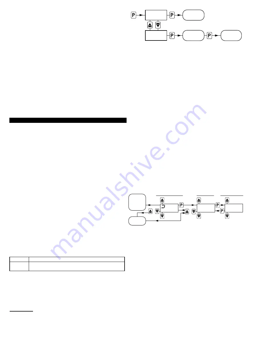
Push key “P”, then release it and the display will visualise
“SP 1”
alternatively to the programmed value.
To modify the value, press “UP” key to increase it or the “DOWN”
key to decrease it.
These keys change the value one digit at a time but if they are
pressed for more than one second, the value increases or
decreases rapidly and, after two seconds in the same condition, the
changing speed increases in order to allow the desired value to be
reached rapidly.
Once the desired value has been reached, by pushing key P it is
possible to exit by the fast programming mode, or (if the instrument
have an output configured as alarm) it is possible to visualise and
modify the
“AL1”
alarm threshold like Set “SP1”.
To exit the fast Set programming it is necessary to push key P, after
the visualisation of the last Set Point, or alternatively, if no key is
pressed for approx. 15 seconds, the display will return to normal
functioning automatically.
Set Point “SP1” can be programmed with a value that is between
the value programmed on par.
“SPLL”
and the one programmed
on par.
“SPHL”.
2.2 - PARAMETERS PROGRAMMING
By pushing key "P" and holding it down for approx. 2 s it is possible
to enter into the main selection menu.
Using the "UP" or DOWN” keys, it is then possible to roll over the
selections:
"OPEr"
To enter into the operating parameters menu
"ConF"
To enter into the configuration parameters menu
(PASSWORD is required)
Once the desired item has been selected, push key “P” to confirm.
Selecting "OPEr" and "ConF" gives the possibility of accessing other
menus containing additional parameters and more precisely :
"OPEr" -
Operating parameters Menu: this normally contains the
Set Point “SP1” and the alarm threshold “AL1” parameters but it can
contain all the desired parameters (see par. 2.3).
"ConF" -
Configuration parameters Menu: this contains all the
operating parameters and the functioning configuration parameters.
ATTENTION: The instrument is programmed in factory with all the
parameters, to exception of the Set Point "SP1" and the alarm
threshold “AL1” , programmable in the menu "ConF" to the purpose
to prevent wrong accidental programming from non experienced
consumers.
Hold
for 2 s
ConF.
OPEr
menu
SET
PASSWORD
ConF
menu
OPEr.
To enter the menu
“ConF”
select the option “ConF”, press the key
“P” and the display will show “0”.
At this request, enter, using keys “UP” and “DOWN”, the number
reported on the last page of this manual and push key “P”.
If an incorrect password is entered, the instrument exit from
programming mode.
If the password is correct, the display will visualise the code
identifying the first group of parameters (“
]
SP
“) and with keys “UP”
and “DOWN” it will be possible to select the desired group of
parameters.
Once the desired group of parameters has been selected, the code
identifying the first parameter of the selected group will be visualised
by pushing the “P” key.
Again using the “UP” and “DOWN” keys, it is possible to select the
desired parameter and, if the key “P” is pressed, the display will
alternatively show the parameter’s code and its programming value,
which can be modified by using the “UP” or “DOWN” keys.
Once the desired value has been programmed, push key “P” once
more: the new value will be memorised and the display will show
only the code of the selected parameter.
By using the “UP” or “DOWN” keys, it is then possible to select a
new parameter (if present) and modify it as described above.
To select another group of parameters, keep the “UP” or “DOWN”
key pressed for approx. 2 s, afterwards the display will return to
visualise the code of the group of parameters.
Release the key and by using the “UP” and “DOWN” keys, it will be
possible to select a new group.
To exit the programming mode, no key should be pressed for
approx. 20 seconds, or keep the “UP” or “DOWN” pressed until exit
from the programming mode is obtained.
The programming and exit modes for the “OPEr” menu are the
same as those described for menu “ConF” with the difference that to
access the menu "OPEr" the Password is not required.
PARAMETERS
PARAMETER GROUPS
SET PARAMETERS
Increase
value
Decrease
value
Hold
for 2 s
O
R
sp1
1
Hold for 2 s
Hold for more than 2 s
O
R
sp .
Previous
Parameter
Next
Parameter
Previous
Group
Next
Group
OPEr
or
OPEr
menu
EXIT
2.3 - PARAMETERS PROGRAMMING LEVELS
The menu “OPEr” normally contains the parameter “SP1”; however
it is possible to make all desired parameters appear or disappear on
this level, by following this procedure:
Enter the menu “ConF” and select the parameter to be made
programmable or not programmable in the menu “OPEr”.
Once the parameter has been selected, if the LED SET is switched
off, this means that the parameter is programmable only in the
menu “ConF”, if instead the LED is on, this means that the
parameter is also programmable in the menu “OPEr”.
To modify the visibility of the parameter, push key “U”: the LED SET
will change its state indicating the parameter accessibility level (on =
menu ”OPEr” and “ConF”; off = menu “ConF” only).
The Set Point ”SP1” and the alarm threshold “AL1” will only be
visible on the Set Point fast programming level (described in par.
2.1) if are present in the menu “OPEr”).
Ascon Tecnologic - TLK 72 B - OPERATING INSTRUCTIONS -
PAG. 2


