


ASCO 3ATS, 3ADTS, 3NTS, 3NDTS
Installation Manual
Page 2
ASCO Power Technologies
381333-404 B
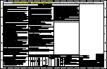
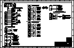
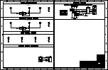
Line Connections
Refer to the wiring diagram provided with the transfer switch.
All wiring must be made in accordance with the National
Electrical Code and local codes.
De-energize the conductors before making any line or
auxiliary circuit connections. Be sure that the Normal
and Emergency line connections are in proper phase
rotation. Place the engine generator starting control in
the OFF position. Make sure engine generator is not in
operation.
Testing Power Conductors
Do not connect the power conductors to the transfer switch
until they are tested. Installing power cables in conduit, cable
troughs, and ceiling-suspended hangers often requires
considerable force. The pulling of cables can damage
insulation and stretch or break the conductor’s strands. For
this reason, after the cables are pulled into position, and before
they are connected, they should be tested to verify that they
are not defective or have been damaged during installation.
Connecting Power Cables
After the power cables have been tested, connect them to the
appropriate terminal lugs on the transfer switch as shown on
the wiring diagram provided with the transfer switch. Make
sure that the lugs provided are suitable for use with the cables
being installed. Standard terminal lugs are solderless screw
type and will accept the wire sizes listed on the drawings
provided with the transfer switch. Be careful when stripping
insulation from the cables, avoid nicking or ringing the
conductor. Remove surface oxides from cables by cleaning
with a wire brush. When aluminum cable is used, apply joint
compound to conductors. Tighten cable lugs to the torque
specified on rating label.
Harnesses
The transfer switch is connected to the left side of the
controller by a plug-in harness.
Auxiliary Circuits
Connect auxiliary circuit wires to appropriate terminals on the
transfer switch as shown on the wiring diagram.
Controller Ground
A grounding wire must be connected to the controller’s lower
left mounting stud. Because the controller is mounted on the
enclosure door, a conductive strap must be used between the
enclosure and the door. This connection provides proper
grounding which does not rely upon the door hinges.
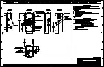
Engine Starting Contacts
The engine control contact connections are located on the
transfer switch for 3ATS & 3NTS or upper right of the
enclosure for 3ADTS & 3NDTS. Connect signal wires to
appropriate terminals as specified on the wiring diagram,
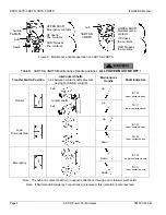
Table A, and shown in Figure 1.
Table A. Engine Start Connections.
When normal
source fails
Terminals on
transfer switch
contact closes
TB1 and TB2
contact opens
TB1 and TB3
Figure 1. Engine start and auxiliary circuit terminal block
TB located on 3ATS & 3NTS transfer switch.
Figure 2. Main contact position indicators on right side.
left side of
transfer switch
terminal block TB
on 3ATS & 3NTS
For 3ADTS & 3NDTS
the terminal block TB
is located in the upper
right side of the
enclosure.
window
indicators
O
is open
C
is closed
Emergency
contacts
Normal
contacts
Summary of Contents for 3ADTS
Page 2: ...ASCO ASCO ...
Page 3: ...ASCO ...
Page 4: ...ASCO ...
Page 5: ...ASCO ...
Page 6: ...ASCO ...
Page 7: ...ASCO ...


