


ASCO 3ATS, 3ADTS, 3NTS, 3NDTS
Installation Manual
Page 4
ASCO Power Technologies
381333-404 B
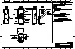
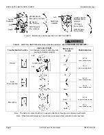
LOWER SHAFT
Normal source
contacts
UP closes
the contacts
DOWN opens
the contacts
hub
hub
frame
handle
UPPER SHAFT
Emergency contacts
UP opens
The contacts
DOWN closes
The contacts
Figure 6. Maintenance handle operation on 3ADTS & 3NDTS
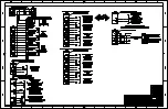
Table B.
3ADTS &
3NDTS
Table B. 3ADTS & 3NDTS Maintenance Handle positions.
ALL POWER MUST BE OFF !
Transfer Switch Position
Interlocked Shafts
Link between contact shafts prevents
closing both N & E contacts
Maintenance
Handle
Shaft Indicators
Normal
E = O
upper contacts open
N = C
lower contacts closed
Load
Disconnected
E = O
upper contacts open
N = O
lower contacts open
Emergency
E = O
upper contacts closed
N = C
lower contacts open
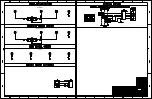
Note: The hub and contact shaft turn in opposite directions through a cam follower mechanism.
Note: If Normal and Emergency connections are reversed, this operation is also reversed.
up
down
up
up
down
down
hub
hub
contact shafts
Summary of Contents for 3ADTS
Page 2: ...ASCO ASCO ...
Page 3: ...ASCO ...
Page 4: ...ASCO ...
Page 5: ...ASCO ...
Page 6: ...ASCO ...
Page 7: ...ASCO ...


