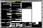


Installation Manual
ASCO 3ATS, 3ADTS, 3NTS, 3NDTS
381333-404 B
ASCO Power Technologies
Page 3
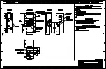
left side of
transfer switch
maintenance
handle
clip
contact shaft hub
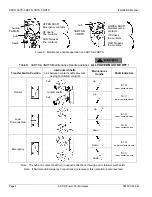
Figure 4. Maintenance handle on 3ATS & 3NTS
left side of
transfer switch
maintenance
handle
clip
Emergency source
contact shaft hub
Hubs shown with
Emergency source
contacts open and
Normal source contacts
closed. See Table B
on page 4.
Normal source
contact shaft hub
Figure 5. Maintenance handle on 3ADTS & 3NDTS
hub
frame
handle
UP closes the
Normal source
contacts (lower)
DOWN closes the
Emergency source
contacts (upper)
Functional Test
The functional test consists of three checks: manual
operation, voltage checks, and electrical operation.
Do these checks in the order presented to avoid
damaging the transfer switch.
1 – Manual Operation
A maintenance handle is provided on the transfer switch for
maintenance purposes only. Manual operation of the transfer
switch should be checked before it is energized (operated
electrically).
Do not manually operate the transfer switch until
both power sources are disconnected: open both
circuit breakers.
1.
After deenergizing both power sources, open the enclosure
door. Locate and remove the maintenance handle from the
clip on the left side of the transfer switch. See Figures 3, 4,
5, & 6. See Figure 2 for the contact position indicators.
2.
Install the handle into the hole in the molded hub. Move
the handle up or down as shown to manually operate the
transfer switch. It should operate smoothly without any
binding. If it does not, check for shipping damage or
construction debris.
3.
3ADTS and 3NDTS have two contact shaft hubs. See
Figures 5 and 6 and Table B.
4.
Return the transfer switch to the Normal position.
Note: If Normal and Emergency connections are reversed this
operation
is also
reversed.
Figure 3. Maintenance handle operation
on 3ATS & 3NTS.
Summary of Contents for 3ADTS
Page 2: ...ASCO ASCO ...
Page 3: ...ASCO ...
Page 4: ...ASCO ...
Page 5: ...ASCO ...
Page 6: ...ASCO ...
Page 7: ...ASCO ...


