Asco 3ADTS Installation Manual Download Page 13

ASCO 3ATS, 3ADTS, 3NTS, 3NDTS 


Installation Manual 

Page 6 

ASCO Power Technologies 

381333-404 B 


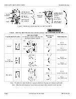
Figure 8.  Transfer button and indicator lights. 


3 – Electrical Operation 

This procedure will check the electrical operation of the 
transfer switch. 


Close the transfer switch enclosure door and 
tighten the screws before you test electrical 
operation. 

Perform steps 1 through 5 at the right.  Observe the status 
lights.  See Figure 8. 


 Black circle means light is on. 


 White circle means light is off. 

NOTE:

  For 3NTS manually start the emergency generator at 

the generator.  Then press the transfer button for load transfer.  
If the inphase transfer feature is activated, transfer may not 
occur immediately.  Transfer will occur when the phase 
relationship between sources is correct.  Press the transfer 
button again for load retransfer to normal, then manually stop 
the generator at the generator. 

Also see User’s Guide 381333-400 for inphase transfer and 
time delay settings in the controller. 

This completes the functional test of the transfer switch.  
Leave the engine-generator starting control in the automatic 
position. 


1

The normal source must be available and the generator 
must be ready to start.  Check that the normal source 
accepted light is on.


2

For 3ATS & 3ADTS press the transfer 
button.  The engine should start and run 
within 15 seconds. For 3NTS & 3NDTS 
the generator must be started manually 
at the generator. 

The emergency source accepted light should come on.


3

For 3ATS & 3ADTS the transfer switch should transfer to 
the emergency position.  The load on emergency light 
should come on and the load on normal light should go 
off.  For 3NTS & 3NDTS press the transfer button for 
load transfer.  For 3ADTS & 3NDTS both lights will be off 
during the delayed-transition transfer time delay.


If the transfer to emergency delay is 
used, the transfer occurs after a time 
delay.  For immediate transfer (bypass 
timer) press the transfer button again.  

4

For 3ATS & 3ADTS the transfer switch should transfer 
back to the normal position.  The load on normal light 
should come on and the load on emergency light should 
go off.  For 3NTS & 3NDTS press the transfer button for 
load retransfer.  For 3ADTS & 3NDTS both lights will be 
off during the delayed-transition transfer time delay.


If the retransfer to normal delay is used 
the retransfer should occur after a time 
delay. For immediate retransfer (bypass 
timer) press the transfer button again. 

5

For 3ATS & 3ADTS the unloaded running delay keeps 
the generator running for a cool-down period.  Then the 
generator should stop and the emergency source 
accepted light should go off.  For 3NTS & 3NDTS 
manually stop the generator at the generator (after a 
cool-down period).


Observe 
these 
lights 

Press this 
button 

Summary of Contents for 3ADTS

Page 1: ...URE COMMON ALARM NOT IN AUTO SIGNALING FEATURES INPHASE TRANSFER FEATURE FOR LOAD TRANSFER SOURCE AVAILABILITY SIGNALS EXTERNAL POWER SUPPLY COMPATIBILITY LOAD CURRENT METERING NON AUTOMATIC MANUAL OPERATION FOUR FUNCTION SOFTWARE BUNDLE REMOTE CONTROL FEATURES ...

Page 2: ...ASCO ASCO ...

Page 3: ...ASCO ...

Page 4: ...ASCO ...

Page 5: ...ASCO ...

Page 6: ...ASCO ...

Page 7: ...ASCO ...

Page 8: ...h for all mounting details including door opening space If bottom cable entry is used the foundation must be prepared so that the conduit stubs are located correctly Refer to the enclosure outline drawing for specified area and location Provide cable bending space and 1 inch minimum clearance to live metal parts When a concrete floor is poured use interlocking conduit spacer caps or a wood or meta...

Page 9: ...d with the transfer switch Be careful when stripping insulation from the cables avoid nicking or ringing the conductor Remove surface oxides from cables by cleaning with a wire brush When aluminum cable is used apply joint compound to conductors Tighten cable lugs to the torque specified on rating label Harnesses The transfer switch is connected to the left side of the controller by a plug in harn...

Page 10: ...s provided on the transfer switch for maintenance purposes only Manual operation of the transfer switch should be checked before it is energized operated electrically Do not manually operate the transfer switch until both power sources are disconnected open both circuit breakers 1 After deenergizing both power sources open the enclosure door Locate and remove the maintenance handle from the clip o...

Page 11: ...e positions ALL POWER MUST BE OFF Transfer Switch Position Interlocked Shafts Link between contact shafts prevents closing both N E contacts Maintenance Handle Shaft Indicators Normal E O upper contacts open N C lower contacts closed Load Disconnected E O upper contacts open N O lower contacts open Emergency E O upper contacts closed N C lower contacts open Note The hub and contact shaft turn in o...

Page 12: ...e settings in the controller 1 Close the normal source circuit breaker The normal source accepted and the load on normal lights should come on 2 Use an accurate voltmeter to check phase to phase and phase to neutral voltages present at the transfer switch normal source terminals 3 Close the emergency source circuit breaker Start generator if necessary The emergency source accepted light should com...

Page 13: ...s the transfer button The engine should start and run within 15 seconds For 3NTS 3NDTS the generator must be started manually at the generator The emergency source accepted light should come on 3 For 3ATS 3ADTS the transfer switch should transfer to the emergency position The load on emergency light should come on and the load on normal light should go off For 3NTS 3NDTS press the transfer button ...

Page 14: ...ns no further lubricating is required Renew factory lubrication if the transfer switch is subjected to severe dust abnormal operating conditions or if the TS coil s is replaced Order lubrication kit 75 100 Check all cable connections retighten them Torque to values shown on the transfer switch label Replacement Parts When ordering replacement parts provide the Serial No Bill of Material No BOM and...

Page 15: ...st 90 of nominal phase to phase voltage between transfer switch terminals EA and EC or EL1 and EL2 for 2 pole switches There are factory settings For 3ATS 3ADTS the transfer switch does not transfer the load to normal source when normal returns or after transfer test Wait for the feature 3A time delay For immediate retransfer press the transfer button bypass timer If inphase transfer is active wai...

Reviews: