background image

7 | 

p a g e


5.4.


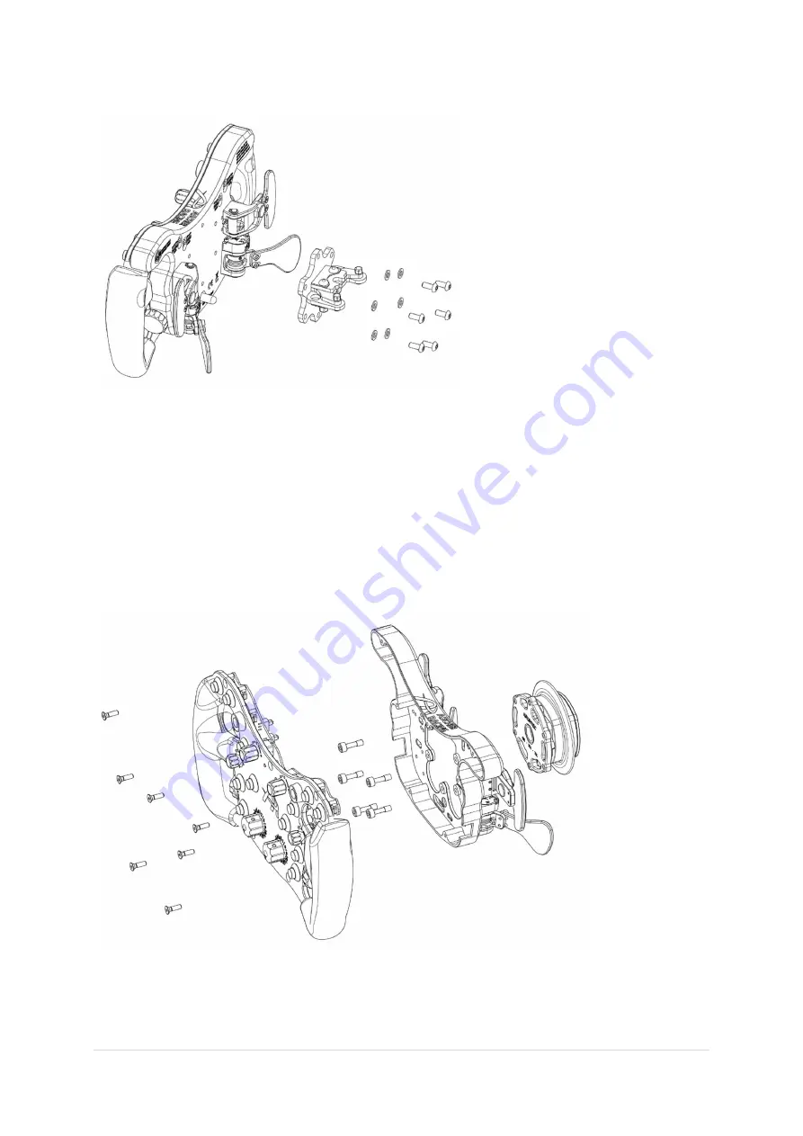
70mm bolt pattern Quick Release – inside mounting 


QRs with either M5 threaded blind holes or other features preventing from conventional mounting 

can be attached from the inside of the wheel casing. 

Captive screws

 are required to bypass the thread 

of the casing. 

First open the steering wheel by removing all (7) M4 screws on the frontplate. Unplug paddle shifters 

and clutches in order to separate the casing from the frontplate assembly. Screw-in (5) captive screws 

into  the  casing  from  the  inside  completely  past  their  thread  engagement.  Then  mount  the  QR  by 

turning each captive screw for 

only half a turn

 in a circular pattern until both opposing surfaces are 

touching. Plug-in cables, reassemble the steering wheel and make sure to not squeeze any cables. 


Summary of Contents for SIMUCUBE F64 Series

Page 1: ...F64 SC V3 steering wheel for racing simulators product manual V1 0 ...

Page 2: ...EEL SIDE Ascher Racing SQR Adapter 6 5 3 70mm bolt pattern Quick Release outside mounting 6 5 4 70mm bolt pattern Quick Release inside mounting 7 6 Getting Started 8 6 1 First Wireless Connection Pairing 8 6 2 Normal Operation 10 6 3 Configure Analog Inputs 10 6 4 Adjust Clutch Bite Point 13 6 5 Mode Switches 13 6 6 Simucube Button 13 7 Battery 14 7 1 Charging 14 7 2 Battery Life 14 8 Paddle Shift...

Page 3: ...ive force bend or pull on the wireless antenna Make sure the steering wheel is mounted securely to your wheel base and screws are tightened properly before use Do not leave the device exposed to a heat source or in a high temperature location such as in the sun in an unattended vehicle To prevent the possibility of damage remove the device from the vehicle or store it out of direct sunlight 1 2 Ba...

Page 4: ...x contains the following components and accessories F64 SC V3 steering wheel USB C to USB A charging cable standard screws and washers for Quick Release mounting sticker sheets for encoders and buttons alternative magnets and spacers ...

Page 5: ...5 p a g e 4 Product Overview ...

Page 6: ...not part of the scope of supply and have to be purchased separately 5 1 SC2 SQR WHEEL SIDE Simucube Adapter 5 2 SC2 SQR WHEEL SIDE Ascher Racing SQR Adapter 5 3 70mm bolt pattern Quick Release outside mounting Standard 70mm bolt pattern Quick Releases with non threaded through holes e g Q1R 70mm wheel side can be mounted as follows QRs with threaded through holes can be mounted similarly by using ...

Page 7: ...pen the steering wheel by removing all 7 M4 screws on the frontplate Unplug paddle shifters and clutches in order to separate the casing from the frontplate assembly Screw in 5 captive screws into the casing from the inside completely past their thread engagement Then mount the QR by turning each captive screw for only half a turn in a circular pattern until both opposing surfaces are touching Plu...

Page 8: ...uring the first 11s after being switched on During this time the left green LED blinks quickly a successful connection is visualized by 3 slow green blinks 1 open True Drive Wireless Wheels Tab 2 Automatic connection mode Connect to previously connected wheel 3 switch ON steering wheel 4 double click Ascher Racing F64 V3 1 2 3 ...

Page 9: ...9 p a g e 4 ...

Page 10: ...the following conditions turning the wheel for more than 10 FFB effects in use pushing any button on the wireless wheel 6 3 Configure Analog Inputs Both analog paddles can be either set up as individual axis e g throttle and brake or as combined axis called dual clutch This mode compares the output of both axis and uses the momentarily greater value Additionally one clutch is defined as master m t...

Page 11: ...11 p a g e 1 2 3 4 ...

Page 12: ...at which the output starts 0 Set this value about 1 2 higher than the Raw value of the resting paddle Deadzone high defines the Raw value at which the output ends 100 Set this value about 1 2 lower than the Raw value of the fully pulled paddle Realistic values are as follows The last step is to define the previously configured wheel axis as a Simucube 2 axis If the axis doesn t show up correctly i...

Page 13: ... and functionality encoder mode switch changes the behavior of the top encoder push button push btn standard mode push button can be used as input in the simulation shift push button can t be used in the simulation o pressing the push button creates an additional encoder output o adjust two controls with one physical encoder o e g turn to adjust ABS push turn to adjust TC rotary mode switch change...

Page 14: ...y Voltage is shown in TrueDrive Overview Tab once connected The battery is expected to last at least 800h in a typical use case Once the battery crosses 3 35V a low Voltage warning is triggered the right LED on the frontplate blinks every 2 minutes 3 fast flashes SC2 gives an audible warning if enabled The remaining driving time at this point is approx 33h It s recommended to not discharge the bat...

Page 15: ...nsuccessful pull the paddle shifter in order to reduce the force between the installed magnets Make sure that no loose magnets are in close proximity in order to avoid magnets crashing into each other unintentionally Depending on the installed combination the shifter force will be approximately 800g 5mm 5mm factory default 570g 5mm 5mm 1 spacer 480g 3mm 3mm 440g 5mm 5mm 2 spacers 340g 3mm 3mm 1 sp...

Page 16: ...16 p a g e 9 Steering Wheel Dimensions ...

Reviews: