background image

55

CONNECTING AH24DB2

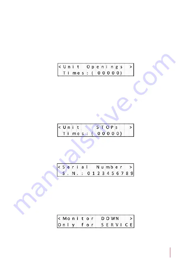
9) UNIT OPENS

It is a diagnostic option that provides historical data.
 
It is very useful to analyze how the device has been used during its lifecycle 
and it provides information about how many movements the device has 
done.

10) UNIT STOPS

It is a diagnostic option that provides historical data. It is very useful to 
analyze how the device has been used during its lifecycle.

It provides information about the number of times that the device has 
been protected and made emergency stops.

11) SERIAL NUMBER

Provides the device's serial number.

The serial number can also be obtained via AHnet and AHlink.

12) MONITOR DOWN

Only use this function as per manufacturer advice.

Summary of Contents for AH10DB2

Page 1: ...User Guide Danish craftmanship Mediterranean soul Technology Serving Design DB2 HDCP compliant retractable monitors for furniture integration ...

Page 2: ...LATIONS AND SECURITY 5 SAFETY INSTRUCTIONS 5 BOX CONTENTS 7 GENERAL AHDB2 8 GENERAL AH24DB2 9 AVAILABLE MODELS 10 INSTALLATION INSTRUCTIONS 12 CONNECTING AHDB2 25 CONNECTING AH24DB2 46 INFORMATION ON DISPOSAL 66 WARRANTY TERMS AND CONDITIONS 67 ...

Page 3: ...rthur Holm product Please read these installation and operating instructions carefully and keep them in a safe place for future consultations We remain at your entire disposal if you have any suggestions Henrik Holm General Manager hholm albiral com ...

Page 4: ... based on quality materials and the latest technology Products which endow meeting and conference rooms with silent ergonomic innovative and aesthetic solutions that integrate into the furniture hang from the walls as works of art or are used as interactive points of information The world of Arthur Holm Arthur Holm offers a selection of unique elegant versatile flexible and ergonomic products that...

Page 5: ...the cable used Do not place anything on the power cord Do not locate this product where a person may walk or trip over the cord EC REGULATIONS AND SECURITY ATTENTION Do not disassemble or modify the device in any way This symbol warns of the presence of dangerous un insulated voltages inside some of the components of sufficient magnitude to expose people to risk of electronic shock This symbol dra...

Page 6: ... the equipment to Rain or water Excessive heat cold or humidity Area exposed to direct sunlight Dirty areas Equipment generating strong magnetic fields Avoid placing open containers of liquid near the equipment Keep a minimum distance of 30 mm in order to have good ventilation Never place above the device any sources of flames such as lighted candles etc If you are using the device in extreme weat...

Page 7: ...pply included in the shipping box This power supply can not be replaced by any other rather than the original one Connections Before connecting the power 1 Install the unit on a table or desk in vertical position 2 Remove the foam protecting piece before connecting the monitor Power connection 1 Plug the power cable from the power supply into an AC socket of 100 240 Vac 50 60Hz 2 Plug the 12V D C ...

Page 8: ...ting user s experience and delivering an exceptional image s quality The monitors are equipped with AH AMMC an auto mechanical calibration movement system and the use of the Arthur Holm s ERT will enable the address configuration of all the monitors installed in a table by simply pressing a button The AHlink app allows a wireless access to the test and adjustment functions without removing the uni...

Page 9: ... equipped with AH AMMC an auto mechanical calibration movement system and the use of the Arthur Holm s ERT will enable the address configuration of all the monitors installed in a table by simply pressing a button The AHlink app allows a wireless access to the test and adjustment functions without removing the unit from the table Highlights TFT Active Matrix display 24 4K Retractable monitor with ...

Page 10: ...ack edged glass Allows its installation in a furniture opening of a maximum width of 24 mm and the monitor housing is flush with the desk once in recessed position One capacitive sensor is located on top of the aluminum frame and a second touch sensor on the screen s glass DVI I and DVI D inputs RS 422 I O ISD Interactive Setup Display USB port for firmware upgrades AH AMMC Automechanical movement...

Page 11: ...B2 TS10DB2 Projected capacitive multi touch screen TS17DB2 Projected capacitive multi touch screen TS22DB2 Projected capacitive multi touch screen TS24DB2 Projected capacitive multi touch screen CABDB2 Min 10 units Black anodised CABDB2 Min 10 units Black anodised CABDB2 Min 10 units Black anodised CAB Min 10 units Black anodised GFDB2 Min 10 units Gold finish GFDB2 Min 10 units Gold finish GFDB2 ...

Page 12: ... except from the instructions given in this document Cutting drilling soldering adding electrical and mechanical components can cause danger and should be avoided by all means Not complying with these directions will result in a loss of the Arthur Holm warranty Albiral Display Solutions S L shall not be held liable for any loss or injury incurred as a result of modifications made to goods by anyon...

Page 13: ...nt the table brackets below the table using the holes indicated IN the corresponding Pattern Hole drawing The screws x6 are not supplied The weight of the monitor is up to 25Kg 55 16 Lbs PAY ATTENTION THAT THE BRACKETS ARE MOUNTED IN THEIR CORRESPONING SIDE ...

Page 14: ...nitor brackets Mount the monitor brackets in their corresponding side using the supplied screws Mount the vertical adjustment screws 2 2 on to the monitor bracket so that the tip of the screw is flushed with the upper side of the monitor bracket ...

Page 15: ...w from above the monitor Dimensions A and B in table brackets and in monitor brackets must be the same 1mm If adjustment is necessary loosen 3 3 Table bracket screws keeping always symmetry regarding to the monitor hole in the table Subsequently tighten the table bracket screws ...

Page 16: ...16 INSTALLATION INSTRUCTIONS Hanging the monitor Mount 2 2 nuts on to both table brackets as indicated in the drawing Hang the monitor above nuts ...

Page 17: ...ng the monitor Tighten each nut gradually until the monitor surface is levelled with the table surface Air gap around the monitor have to be 2mm 0 08 Otherwise the monitor could come in contact with the table while opening and be damaged ...

Page 18: ...se fine centring of the monitor is necessary Veneer Guide The DB2V is prepared to be mounted from below the table with a Veneer finishing on the top of the monitor to match the table The Veneer is not supplied The Veneer option V1 V2 V3 are available under request ...

Page 19: ...ways Option V1 Veneer The veneer thickness must be 4mm 0 15 and the copper cylinder will be leveled with table surface Option V2 Veneer Distance Plate For Veneers Thickness of 1mm 0 04 or less It will be necessary a Distance Plate to hide the touch button copper cylinder ...

Page 20: ...20 INSTALLATION INSTRUCTIONS Option V3 Veneer The veneer thickness must be 5mm 0 19 A mechanised blind hole will be necessary to hide the touch button copper cylinder ...

Page 21: ...wo surfaces are touching each other in the whole length To make easier the adjustment the height of the touch button can be barely adjusted 2 Clean the top surface of the metal monitor housing and the bottom surface of the Veneer 3 Glue the Veneer Double side tape or glue can be used depending on the kind of materials are going to be jointed The pressure applied must not exceed 1 Kg evenly distrib...

Page 22: ...istance Plate surface To make easier the adjustment the height of the copper cylinder can be barely adjusted 2 Clean the top surface of the metal monitor housing and the bottom surface of the Distance Plate 3 Glue the Veneer Double side tape or glue can be used depending on the kind of materials are going to be jointed Double side tape or glue used can t be thicker than 0 2 0 25mm 0 008 0 01 The p...

Page 23: ...and the bottom surface of the Veneer 5 Glue the Veneer Double side tape or glue can be used depending on the kind of materials are going to be The total thickness of Veneer glue used can t be thicker than 1mm 0 04 Option 2 Cut Out DB2 Veneer cut out DB2 Distance plate cut out ...

Page 24: ... hole depth in the Veneer is correct To make easier the adjustment the height of the copper cylinder can be barely adjusted 2 Clean the top surface of the metal monitor housing and the bottom surface of the Veneer 3 Glue the Veneer Double side tape or glue can be used depending on the kind of materials are going to be jointed Double side tape or glue used can t be thicker than 0 2 0 25mm 0 008 0 0...

Page 25: ...ROLS IR sensor The IR sensor is located on the lower side of the screen Monitor movement controls On the upper panel body and on front glass there is a button to control the down monitor movements and the screen tilting angle ...

Page 26: ...nitor to raise the display Make sure that no objects are located on top of the monitor 2 Tilting the screen Press and hold the sensor on the top of the monitor to adjust the desired tilt angle 3 Retracting the monitor Press the button on the lower part of the screen to retract the monitor ...

Page 27: ...Activates the OSD menu on screen UP Control up on the OSD menu DOWN Control down on the OSD menu LEFT Control left on the OSD menu RIGHT Control right on the OSD menu OK Selects the function on the OSD menu When the OSD menu is not active on screen selects the input source ...

Page 28: ... available for the monitor Press the OK button to confirm When a function is selected press the LEFT and RIGHT buttons in order to change the parameter of the function Press the MENU button to access to the main menu Picture Picture Mode Adjusts the mode of the image Dynamic Standard Mild User Contrast Brightness Colour Sharpness Tint Colour Temperature Adjusts the colour of the image Cool Medium ...

Page 29: ...s the image noise filter Off Low Medium High Default Screen Only for analogue signals Auto Adjust Horizontal Position Vertical Position Size Phase Backlight Adjusts the backlight screen s level Colour Range Adjusts the colour range 0 255 16 235 ...

Page 30: ...rameters to the initial factory parameters Blending OSD window transparency Low Medium High Off OSD Duration Adjusts the time that the OSD menu window remains on the screen Software Update USB Port to use for firmware s upgrade Mirror 0 Image with no flip 1 Vertical flip 2 Horizontal flip 3 Rotate ...

Page 31: ... and historical data of the device To start using it WELCOME DISPLAY DATA 1 Bootloader Version The display will show a Bootloader Version message example Bootl Ver 1 01 Bootloader is a program which allows the system to be able to update itself The ISD has a Bootloader and therefore is capable of updating to new versions in order to constantly improve the user experience ...

Page 32: ...et address which will be accompanied by an acoustic signal BEEP example Address 001 Once the signal has been heard the UP DOWN buttons will allow the user to scroll through all the variety of menus that the device contains To enter into any specific menu simply press the OK button How to modify the values within each menu The values can be selected through the UP DOWN buttons To save the selected ...

Page 33: ... must be set from 1 to 60 2 VIDEO INPUT SELECTION The device provides the following inputs DVI1 DVI I DVI A and DVI1 D DVI2 DVI D DVI 2D This menu allows the selection of 1 of these 3 inputs 3 MONITOR BRIGHTNESS Brightness level 0 100 4 MONITOR CONTRAST Contrast level 0 100 ...

Page 34: ...the position of the device 7 SENSORS INFORMATION It is a diagnostic option that informs about the internal state of the sensors 8 AHnet INFORMATION This menu is useful for programing and diagnose It provides information about the AHnet command that has been received by the device Example AHnet 0 FA 1 01 2 01 3 01 4 00 ...

Page 35: ...ne 10 UNIT STOPS It is a diagnostic option that provides historical data It is very useful to analyze how the device has been used during its lifecycle It provides information about the number of times that the device has been protected and made emergency stops 11 SERIAL NUMBER Provides the device s serial number The serial number can also be obtained via AHnet and AHlink 12 MONITOR DOWN Only use ...

Page 36: ... speed and protection thresholds 14 AHLink Activates AHlink FIRMWARE UPDATE To update the FW version To start the update connect a PC with the APP AH_FW Device Setting Tool to the device through the USB port Proceed with the following steps Unplug the PSU Wait for 1 minute Press and hold the OK button Plug in the PSU A message will appear on the LCD screen when the connection is ready Start updati...

Page 37: ... of the RS422 bus AHnet RJ45 CAT6 connector for addressable RS422 control There is a loop through connector to use as signal RS422 output Up to 30 monitors can be connected on the same RS422 bus Service Used for firmware s upgrade DVI 1 DVI A DVI I input signal Connect a DVI digital input signal and select DVI 1 on the OSD monitor menu Use a DVI to VGA adaptor to connect an ARGB analogue input sig...

Page 38: ...ta TX 3 Data RX 4 NC 5 NC 6 Data RX 7 NC 8 NC Connection PINS 1 2 The units respond PINS 3 6 The units receive instructions Protocol to control the monitor by addressable RS422 bus You can connect up to 30 monitors on the same RS422 bus You can use an AH ERT interface to control the RS422 bus The units should have a set address and the address must start by 1 Maximum cable length between ends 500 ...

Page 39: ...XX 02 01 00 FA XX 02 00 00 SCREEN OFF FB XX 02 00 00 FA XX 03 01 00 DVI A SELECTION FB XX 03 01 00 FA XX 03 00 00 DVI 1 SELECTION FB XX 03 00 00 FA XX 03 03 00 DVI 2 SELECTION FB XX 03 03 00 FA XX 04 01 00 BUTTON LOCK FB XX 04 01 00 FA XX 04 00 00 BUTTON UNLOCK FB XX 04 00 00 FA XX 14 00 00 INQUIRY CONTROL BYTE FB XX 14 CB1 CB2 XX Number of the monitor address Up to 30 monitors for each RS422 BUS ...

Page 40: ...TING AHDB2 CB1 BITE 7 6 5 4 3 2 1 0 CLOSED 1 1 0 1 OPENED 0 1 0 1 SCREEN ON 1 SCREEN OFF 0 DVI A 0 0 DVI 1 D 1 1 DVI 2 D 1 0 PROTECTION STOP 1 MONITOR OK 0 CB2 BITE 7 6 5 4 3 2 1 0 BUTTON LOCK 1 BUTTON UNLOCK 0 ...

Page 41: ... each RS422 BUS ZZ Level of the function selected 00 99 Dec COMMAND DESCRIPTION RESPONSE FA XX 15 01 ZZ SET BACKLIGHT LEVEL FB XX 15 01 ZZ FA XX 16 01 ZZ SET CONTRAST LEVEL FB XX 16 01 ZZ FA XX 17 01 ZZ SET BRIGHTNESS LEVEL FB XX 17 01 ZZ XX Number of the monitor address Up to 30 monitors for each RS422 BUS ZZ Level of the function selected 00 99 Dec To send an order to all the monitors you must u...

Page 42: ...46 875 75 000 Progressive 1024x768 60Hz 48 363 60 005 Progressive 1024x768 70Hz 56 476 70 070 Progressive 1024x768 75Hz 60 023 75 030 Progressive 1280x720 60Hz 44 772 59 855 Progressive 1360x768 60Hz 47 720 59 799 Progressive 1280x1024 60Hz 63 981 60 020 Progressive 1600x1200 60Hz 75 000 60 000 Progressive 1680x1050 60Hz 64 742 59 946 Progressive 1920x1080 60Hz 67 500 60 000 Progressive ...

Page 43: ...the OK button to activate the AHlink signal on the unit When the AHlink signal is activated the sound of 5 beeps will indicate that the AHlink signal is active on the unit The wireless AHlink signal automatically deactivates when there is no device connected during more than 2 minutes When the AHlink deactivates you will hear a long Beep sound To control and set up your AH product with AHlink plea...

Page 44: ...ignal might no longer be active The AHlink name always begins with the characters AH followed by the four last MAC AHlink address You must select the AH device After selecting the AH device the first page will upload on your screen This page is used for the basic installation setup ...

Page 45: ...ightness adjustments SAVE VALUES Memorises the backlight contrast and brightness values AHLINK OFF Turns off the AHlink signal COMMAND Information of the last AHnet command received from RS422 port SENSORS Indicates sensor status S1 indicates the screen up position S2 Indicates the 110º tilt screen position S3 Indicates the 90º tilt screen position AHNET ADDRESS AH address settings POSITION Screen...

Page 46: ...TROLS IR sensor The IR sensor is located on the lower side of the screen Monitor movement controls On the upper panel body and on front glass there is a button to control the down monitor movements and the screen tilting angle ...

Page 47: ...onitor to raise the display Make sure that no objects are located on top of the monitor 2 Tilting the screen Press and hold the sensor on the top of the monitor to adjust the desired tilt angle 3 Retracting the monitor Press the button on the lower part of the screen to retract the monitor ...

Page 48: ... function MENU Activates the OSD menu on screen SOURCE Selects the input source signal UP Control up on the OSD menu DOWN Control down on the OSD menu LEFT Control left on the OSD menu RIGHT Control right on the OSD menu OK Selects the function on the OSD menu VOLUME Control up down volume ...

Page 49: ...ss level Contrast Adjusts the contrast level Sharpness Adjusts the sharpness Display Display rotate Rotates the image on screen 0 180 LR Mirror UD Mirror Colour Gamma Adjusts the picture gamma OFF 1 8 2 0 2 2 2 4 Temperature Adjusts the colour temperature 9300 7500 6500 5800 sRGB user Colour Effect Adjusts the colour filter Standard Game Movie Photo Vivid User Hue Adjusts the image HUE ...

Page 50: ...ction of the HDR mode OFF AUTO HDR 2084 Dark enhance ON OFF Audio Not used on this project Other Reset resets to factory values Menu time Adjusts the OSD on screen time OSD H position OSD window horizontally position adjust OSD V position OSD window vertically position adjust Transparency OSD window transparency adjust Fan control No function Information Signal input information ...

Page 51: ...e and historical data of the device To start using it WELCOME DISPLAY DATA 1 Bootloader Version The display will show a Bootloader Version message example Bootl Ver 1 01 Bootloader is a program which allows the system to be able to update itself The ISD has a Bootloader and therefore is capable of updating to new versions in order to constantly improve the user experience ...

Page 52: ...net address which will be accompanied by an acoustic signal BEEP example Address 001 Once the signal has been heard the UP DOWN buttons will allow the user to scroll through all the variety of menus that the device contains To enter into any specific menu simply press the OK button How to modify the values within each menu The values can be selected through the UP DOWN buttons To save the selected...

Page 53: ...s must be set from 1 to 60 2 VIDEO INPUT SELECTION The device provides the following inputs DVI1 DVI I DVI A and DVI1 D DVI2 DVI D DVI 2D This menu allows the selection of 1 of these 3 inputs 3 MONITOR BRIGHTNESS Brightness level 0 100 4 MONITOR CONTRAST Contrast level 0 100 ...

Page 54: ... the position of the device 7 SENSORS INFORMATION It is a diagnostic option that informs about the internal state of the sensors 8 AHnet INFORMATION This menu is useful for programing and diagnose It provides information about the AHnet command that has been received by the device Example AHnet 0 FA 1 01 2 01 3 01 4 00 ...

Page 55: ...one 10 UNIT STOPS It is a diagnostic option that provides historical data It is very useful to analyze how the device has been used during its lifecycle It provides information about the number of times that the device has been protected and made emergency stops 11 SERIAL NUMBER Provides the device s serial number The serial number can also be obtained via AHnet and AHlink 12 MONITOR DOWN Only use...

Page 56: ...e speed and protection thresholds 14 AHLink Activates AHlink FIRMWARE UPDATE To update the FW version To start the update connect a PC with the APP AH_FW Device Setting Tool to the device through the USB port Proceed with the following steps Unplug the PSU Wait for 1 minute Press and hold the OK button Plug in the PSU A message will appear on the LCD screen when the connection is ready Start updat...

Page 57: ...ECTING AH24DB2 INPUT CONNECTORS DP2 Display port input signal connector DP1 Display port input signal connector HDMI2 HDMI input signal connector HDMI1 HDMI input signal connector HP OUT Salida de auriculares ...

Page 58: ...ata TX 3 Data RX 4 NC 5 NC 6 Data RX 7 NC 8 NC Connection PINS 1 2 The units respond PINS 3 6 The units receive instructions Protocol to control the monitor by addressable RS422 bus You can connect up to 30 monitors on the same RS422 bus You can use an AH ERT interface to control the RS422 bus The units should have a set address and the address must start by 1 Maximum cable length between ends 500...

Page 59: ...2 00 00 SCREEN OFF FB XX 02 00 00 FA XX 03 00 00 HDMI1 SELECTION FB XX 03 00 00 FA XX 03 03 00 HDMI2 SELECTION FB XX 03 01 00 FA XX 03 02 00 DP1 SELECTION FB XX 03 02 00 FA XX 03 04 00 DP2 SELECTION FB XX 03 03 00 FA XX 04 01 00 BUTTON LOCK FB XX 04 01 00 FA XX 04 00 00 BUTTON UNLOCK FB XX 04 00 00 FA XX 14 00 00 INQUIRY CONTROL BYTE FB XX 14 CB1 CB2 XX Number of the monitor address Up to 30 monit...

Page 60: ...NG AH24DB2 CB1 BITE 7 6 5 4 3 2 1 0 CLOSED 1 1 0 1 OPENED 0 1 0 1 SCREEN ON 1 SCREEN OFF 0 HDMI1 1 1 HDMI2 1 0 DP1 0 1 DP2 0 0 PROTECTION STOP 1 MONITOR OK 0 CB2 BITE 7 6 5 4 3 2 1 0 BUTTON LOCK 1 BUTTON UNLOCK 0 ...

Page 61: ...r each RS422 BUS ZZ Level of the function selected 00 99 Dec COMMAND DESCRIPTION RESPONSE FA XX 15 01 ZZ SET BACKLIGHT LEVEL FB XX 15 01 ZZ FA XX 16 01 ZZ SET CONTRAST LEVEL FB XX 16 01 ZZ FA XX 17 01 ZZ SET BRIGHTNESS LEVEL FB XX 17 01 ZZ XX Number of the monitor address Up to 30 monitors for each RS422 BUS ZZ Level of the function selected 00 99 Dec To send an order to all the monitors you must ...

Page 62: ...0i 1768x992 30 29 25 1080p 1680x1050 60 59 50 24 23 1080i 1680x1050 30 29 25 1080p 1600x1024 60 59 50 24 23 1080i 1600x1024 30 29 25 1080p 1600x900 60 59 50 24 23 1080i 1600x900 30 29 25 1080p 1440x900 60 59 50 24 23 1080i 1440x900 30 29 25 1080p 1366x768 60 59 50 24 23 1080i 1366x768 30 29 25 1080p 1360x768 60 59 50 24 23 1080i 1360x768 30 29 25 720p 1280x720 60 59 50 720p 1176x664 60 59 50 576p ...

Page 63: ... the OK button to activate the AHlink signal on the unit When the AHlink signal is activated the sound of 5 beeps will indicate that the AHlink signal is active on the unit The wireless AHLink signal automatically deactivates when there is no device connected during more than 2 minutes When the AHLink deactivates you will hear a long Beep sound To control and set up your AH product with AHLink ple...

Page 64: ...signal might no longer be active The AHLink name always begins with the characters AH followed by the four last MAC AHLink address You must select the AH device After selecting the AH device the first page will upload on your screen This page is used for the basic installation setup ...

Page 65: ...T Brightness adjustments SAVE VALUES Memorises the backlight contrast and brightness values AHLINK OFF Turns off the AHlink signal COMMAND Information of the last AHnet command received from RS422 port SENSORS Indicates sensor status S1 indicates the screen up position S2 Indicates the 110º tilt screen position S3 Indicates the 90º tilt screen position AHNET ADDRESS AH address settings POSITION Sc...

Page 66: ...ll help save valuable resources and prevent any potential negative effects on human health and the environment which could otherwise arise from inappropriate waste handling Please contact your local authority for further details of your nearest designated collection point Penalties may be applicable for incorrect disposal of this waste in accordance with national legislation For business users in ...

Page 67: ...bour costs Albiral Display Solutions covers the labour costs to replace any defective parts during the validity of this warranty 5 Transport costs 5 1 In the case that a manufacturing defect occurs within 90 days after the purchase date both freight and insurance costs will be paid by Albiral Display Solutions Although Albiral Display Solutions S L pays for freight and insurance costs Albiral Disp...

Page 68: ...The beneficiary of the warranty will have to return the product with the original packaging to warranty there are no damages during transportation 10 The warranty is not valid if the beneficiary of the warranty does not include an RMA form and a copy of the purchasing invoice Please note that laws vary from country to country and the same provisions of this warranty may not apply to you If you hav...

Page 69: ...pòlit de Voltregà 08512 Barcelona Spain tel 34 93 850 23 76 23 83 fax 34 93 850 25 50 23 72 web www arthurholm com e mail marketing arthurholm com This manual can be modified without previous notice ENG November 2020 P27178ITEP P27178RUPC P27178USPC P27284DEEP P27284EPPC P27284ESEP P27284GBEP P27284RUPC P27284USPC P27715ESEP P28089DEEP P28089ESEP P28089ITEP P28089USPC P28090EP00 P31160ESES P31160P...

Reviews: