16
CI10-AL
En
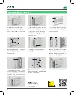
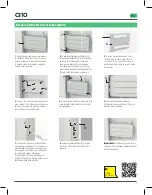
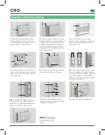
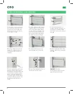
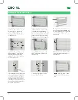
3.
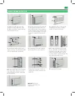
Fix the adhesive strips (I) to the rear
of the base plate (B) or the shims (C) to
suitably position it on the door before
drilling.
1.
Calculate the position where you want
to install the lock, always inside the door.
Place the adhesive spacer (H) as shown in
the image, stuck to the body of the lock.
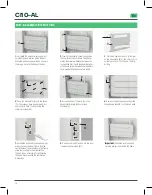
2.
Next to the adhesive spacer (H), position
the trim (F) on the door frame. The spacer
marks the minimum distance between the
lock and the trim. If both these parts are not
at the same height, you must use the shims
(C) to wedge the lock as shown in step 4.
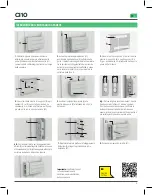
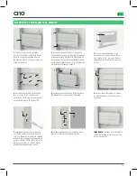
6.
Remove the adhesive spacer. Position
the adhesive disks (G) on the lock’s bolts.
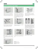
4.
Once the base plate (B) and the shims
(C), if necessary, have been pre-positio-
ned, drill and fi x to the door using the
screws provided (M).
5.
Screw the body of the lock (A) to the
base plate (B) using the four screws
provided (L).
7.
Extend the bolts and the adhesive disks
will be stuck on the door frame. Drill the
central holes of the disk stuck to the frame
using tools suited to the material. Use
the disk (G) as a template for perforating
the holes. Never exceed the template’s
dimensions.
8.
Position the trim (F) and fi x it to the door
frame using the screws (M).
Important:
Check the lock functions
correctly, always from inside the home.
BUILT-IN ASSEMBLY INSTRUCTIONS
I
B
H
H
F
G
L
A
B
G
F
M
M
B

