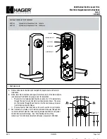


4 3/8"
111
2 3/16"
56
3 5/8"
92
.687
17
.687
17
1/2"
LHR HANDING
(SEE NOTE)
13
1/2"
RHR HANDING
(SEE NOTE)
13
TRIM MOUNTING HOLES (4X)
DRILL
1/2" HOLE
CL
4500 Series Electric Lever Trim
Electrical Supplemental Instructions
Grade 1
I-ED00370
DEVICES COVERED IN THIS DOCUMENT:
45ET-EL
Cylinder Escutcheon Lever Trim - Fail Safe
45ET-EU
Cylinder Escutcheon Lever Trim - Fail Secure
1. PREPARE DOOR
A. Follow exit device instructions and template to prepare door and frame for
installation.
B. Follow lever trim instructions and special electric version of the trim template
(see document T-ED00372) to prepare door for installation.
i. The electric trim template identifies the location of a 1/2” diameter hole
through the door for wire transfer to exit device side of door. The wires
are then routed through the exit device, into the door raceway to power
transfer device (electric hinge).
ii. The wire transfer hole is handed, so be sure to use the correct location.
C. Door fabricator to provide a 3/8” diameter (minimum) raceway through door
to allow insertion of electrical wires running between exit device and power
transfer device (electric hinge). See “Wire Routing and Door Prep
Instructions” for 4500 Series Electric Exit Devices, document I-ED00367.
REV 3
Page 1 of 3
SOLENOID BRACKET
SOLENOID
PIVOT LEVER
LOCKING LINK
MOUNTING POST
27390028