507029-03
Page 50 of 68
Issue 1622
High Altitude Information
NOTE:
In Canada, certification for installation at elevations
over 4500 feet (1372 m) is the jurisidiction of local authorities.
These units require no manifold pressure adjustments for
operation at altitudes up to 7,500 feet (2286 m) above sea
level. Table 27 lists conversion kit requirements, pressure
switch requirements and manifold pressures at all altitudes.
The combustion air pressure switch is factory set and
requires no adjustment.
Proper Combustion
Furnace should operate a minimum of 15 minutes with cor-
rect manifold pressure and gas flow rate begore checking
combustion. Take combustion sample beyond the flue outlet
and compare to the tables below. The maximum carbon
monoxide reading should not exceed 100 ppm.
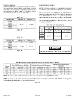
Conversion Kit Requirements
Table 27
Model
Input
Size
LP/Propane
Kit
High Altitude Pressure Switch Kit
0 - 10,000
(0-3048 m)
0 - 7,500
(0 - 2286 m)
7,501 - 10,000
(2287 - 3048m)
70
68W77
Not required
14T67
90
110
135
CAUTION
DO NOT
attempt to make adjustments to the gas valve.
NOTE:
The values given in table are measurements only. The gas valve should
NOT
be adjusted.
NOTE:
A natural to LP/propane gas changeover kit (Table 27) is necessary to convert this unit. Refer to the changeover
kit installation instructions for the conversion procedure.
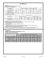
Table 28
Manifold and Operating Signal Pressures in inches 0-7500 ft (0-2286 m)
High Fire
Table 25
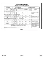
Table 26
Low Fire
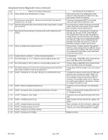
Summary of Contents for A97DSMV
Page 3: ...507029 03 Page 3 of 68 Issue 1622 A97DSMV Exploded View Figure 1...
Page 13: ...507029 03 Page 13 of 68 Issue 1622 OUTDOOR TERMINATION KITS USAGE Table 3...
Page 24: ...507029 03 Page 24 of 68 Issue 1622 Figure 29...
Page 27: ...507029 03 Page 27 of 68 Issue 1622 Figure 36 Trap Drain Assembly Using 1 2 PVC or 3 4 PVC...
Page 33: ...507029 03 Page 33 of 68 Issue 1622 Figure 43 Typical A97DSMV Wiring Diagram...
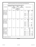
Page 34: ...507029 03 Page 34 of 68 Issue 1622 Figure 45...
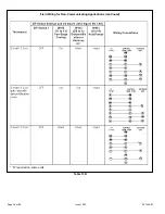
Page 35: ...507029 03 Page 35 of 68 Issue 1622 Figure 46...
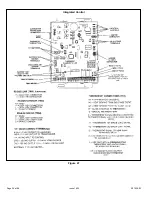
Page 36: ...507029 03 Page 36 of 68 Issue 1622 Figure 47 Integrated Control...
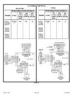
Page 40: ...507029 03 Page 40 of 68 Issue 1622 Low Voltage Field Wiring Table 14 Single Stage 2 Stage...
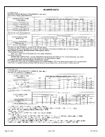
Page 44: ...507029 03 Page 44 of 68 Issue 1622 BLOWER DATA...
Page 57: ...507029 03 Page 57 of 68 Issue 1622...
Page 58: ...507029 03 Page 58 of 68 Issue 1622...
Page 59: ...507029 03 Page 59 of 68 Issue 1622...
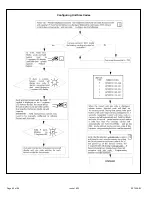
Page 60: ...507029 03 Page 60 of 68 Issue 1622 Configuring Unit Size Codes...
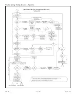
Page 61: ...507029 03 Page 61 of 68 Issue 1622 Troubleshooting Heating Sequence of Operation...
Page 62: ...507029 03 Page 62 of 68 Issue 1622 Troubleshooting Heating Sequence of Operation continued...
Page 63: ...507029 03 Page 63 of 68 Issue 1622 Troubleshooting Heating Sequence of Operation continued...
Page 64: ...507029 03 Page 64 of 68 Issue 1622 Troubleshooting Heating Sequence of Operation continued...
Page 65: ...507029 03 Page 65 of 68 Issue 1622 Troubleshooting Cooling Sequence of Operation...
Page 66: ...507029 03 Page 66 of 68 Issue 1622 Troubleshooting Continuous Fan Sequence of Operation...

