


507029-03
Page 20 of 68
Issue 1622
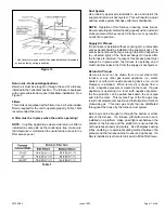
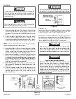
General Guidelines for Vent Terminations
In Direct Vent applications, combustion air is taken from
outdoors and the flue gases are discharged to the outdoors.
This gas furnace is classified as a direct vent, Category IV
gas furnace.
In Direct Vent applications, the vent termination is limited by
local building codes. In the absence of local codes, refer to
the current National Fuel Gas Code ANSI Z223-1/NFPA 54
in U.S.A., and current CSA-B149 Natural Gas and Propane
Installation Codes in Canada for details.
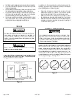
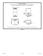
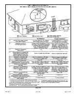
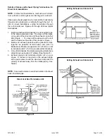
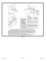
Position termination according to location given in Figure
20. In addition, position termination so it is free from any
obstructions and 12” above the average snow accumulation.
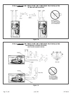
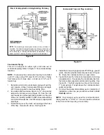
At vent termination, care must be taken to maintain
protective coatings over building materials (prolonged
exposure to exhaust condensate can destroy protective
coatings). It is recommended that the exhaust outlet not be
located within 6 feet (1.8m) of a condensing unit because
the condensate can damage the painted coating.
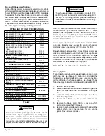
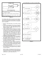
NOTE:
See Table
6
for maximum allowed exhaust pipe
length without insulation in unconditioned space during
winter design temperatures below 32
°
F
(O
°
C)
.
If equired
exhaust pipe should be insulated with
1
/
2
”
(13mm)
Armaflex or equivalent
.
In extreme cold climate areas
,
3
/
4
”
(19mm) Armaflex or equivalent may be necessary
.
Insulation on outside runs of exhaust pipe must be painted
or wrapped to protect insulation from deterioration
.
Exhaust
pipe insulation may not be necessary in some specific
applications
.
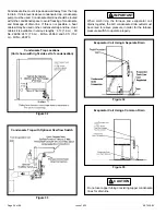
Do not use screens or perforated metal in exhaust
terminations. Doing so will cause freeze-ups and may
block the terminations.
IMPORTANT
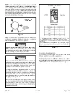
FOR CANADIAN INSTALLATIONS ONLY:
In accorddance to CSA International B149 installation
codes, the minimum allowed distance between the
combustion air intake inlet and the exhaust outlet of
other appliances shall not be less than 12 inches (305
mm).
IMPORTANT
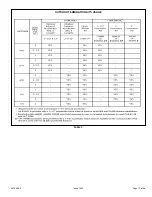
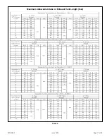
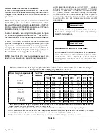
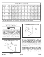
Table 6
Maximum Allowable Vent pipe Length without Insulation in Unconditioned Space for Winter Design
Temperatures Modulating High Efficiency Furnace
Winter Design Temperatures
1
ºF (ºC)
Vent Pipe
Diameter
070
090
110
135
32 to 21
(0 to -6)
PVC
2
PP
PVC
2
PP
PVC
2
PP
PVC
2
PP
2 in.
11
9
14
12
18
15
N/A
N/A
2-1/2 in.
7
N/A
10
N/A
12
N/A
N/A
N/A
3 in.
N/A
N/A
6
6
8
8
13
13
20 to 1
(-7 to -17)
2 in.
N/A
N/A
6
4
8
6
N/A
N/A
2-1/2 in.
N/A
N/A
N/A
N/A
N/A
N/A
N/A
N/A
3 in.
N/A
N/A
N/A
N/A
N/A
N/A
N/A
N/A
0 to -20
(-18 to -29)
2 in.
N/A
N/A
N/A
N/A
N/A
N/A
N/A
N/A
2-1/2 in.
N/A
N/A
N/A
N/A
N/A
N/A
N/A
N/A
3 in.
N/A
N/A
N/A
N/A
N/A
N/A
N/A
N/A
1
Refer to 99% Minimum Design Temperature table provided in the current edition of the ASHRAE Fundamentals Handbook.
2
Poly-Propylene vent pipe (PP) by Duravent and Centrotherm
NOTE - Concentric terminations are the equivalent of 5’ and should be considered when measuring pipe length.
NOTE- Maximum uninsulated vent lengths listed may include the termination (vent pipe exterior to the structure ) and cannot
exceed 5 linear feet or the maximum allowable intake or exhaust vent length listed in table 5 or 6.
NOTE - If insulation is required an unconditioned space, it must be located on the pipe closed to the furnace.
Summary of Contents for A97DSMV
Page 3: ...507029 03 Page 3 of 68 Issue 1622 A97DSMV Exploded View Figure 1...
Page 13: ...507029 03 Page 13 of 68 Issue 1622 OUTDOOR TERMINATION KITS USAGE Table 3...
Page 24: ...507029 03 Page 24 of 68 Issue 1622 Figure 29...
Page 27: ...507029 03 Page 27 of 68 Issue 1622 Figure 36 Trap Drain Assembly Using 1 2 PVC or 3 4 PVC...
Page 33: ...507029 03 Page 33 of 68 Issue 1622 Figure 43 Typical A97DSMV Wiring Diagram...
Page 34: ...507029 03 Page 34 of 68 Issue 1622 Figure 45...
Page 35: ...507029 03 Page 35 of 68 Issue 1622 Figure 46...
Page 36: ...507029 03 Page 36 of 68 Issue 1622 Figure 47 Integrated Control...
Page 40: ...507029 03 Page 40 of 68 Issue 1622 Low Voltage Field Wiring Table 14 Single Stage 2 Stage...
Page 44: ...507029 03 Page 44 of 68 Issue 1622 BLOWER DATA...
Page 57: ...507029 03 Page 57 of 68 Issue 1622...
Page 58: ...507029 03 Page 58 of 68 Issue 1622...
Page 59: ...507029 03 Page 59 of 68 Issue 1622...
Page 60: ...507029 03 Page 60 of 68 Issue 1622 Configuring Unit Size Codes...
Page 61: ...507029 03 Page 61 of 68 Issue 1622 Troubleshooting Heating Sequence of Operation...
Page 62: ...507029 03 Page 62 of 68 Issue 1622 Troubleshooting Heating Sequence of Operation continued...
Page 63: ...507029 03 Page 63 of 68 Issue 1622 Troubleshooting Heating Sequence of Operation continued...
Page 64: ...507029 03 Page 64 of 68 Issue 1622 Troubleshooting Heating Sequence of Operation continued...
Page 65: ...507029 03 Page 65 of 68 Issue 1622 Troubleshooting Cooling Sequence of Operation...
Page 66: ...507029 03 Page 66 of 68 Issue 1622 Troubleshooting Continuous Fan Sequence of Operation...


