507029-03
Page 5 of 68
Issue 1622
For installation in a residential garage, the furnace must be
installed so that the burner(s) and the ignition source are
located no less than 18 inches (457 mm) above the floor.
The furnace must be located or protected to avoid physical
damage by vehicles. When a furnace is installed in a public
garage, hangar, or other building that has a hazardous
atmosphere, the furnace must be installed according to
recommended good practice requirements and current
National Fuel Gas Code or CSA B149 standards.
Note:
Furnace must be adjusted to obtain a temperature
rise (100% percent capacity) within the range (s) specified
on the unit nameplate. Failure to do so may cause erratic
limit operation and may also result in premature heat
exchanger failure.
This A97DSMV furnace must be installed so that its electrical
components are protected from water.
Installed in Combination with a Cooling Coil
When this furnace is used with cooling units, it shall be
installed in parallel with, or on the upstream side of, cooling
units to avoid condensation in the heating compartment.
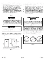
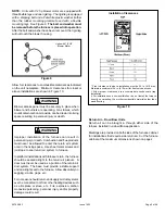
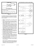
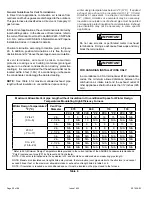
With a parallel flow arrangement, a damper (or other means
to control the flow of air) must adequately prevent chilled
air from entering the furnace. If the damper is manually
operated, it must be equipped to prevent operation of either
the heating or the cooling unit, unless it is in the full
HEAT
or
COOL
setting. See Figure 3.
The A97DSMV furnace may be installed in alcoves, closets,
attics, basements, garages, crawl spaces and utility rooms.
This furnace design has not been CSA Certified for
installation in mobile homes, recreational vehicles, or
outdoors.
Use of Furnace as Construction Heater
These units are not recommended for use as a construction
heater during any phase of construction. Very low return air
temperature, harmful vapors and operation of the unit with
clogged or misplaced filters will damage the unit.
These units may be used for heating of buildings or
structures under construction, if the following conditions
are met:
•
The vent system must be permanently installed per
these installation instructions.
•
A room thermostat must control the furnace. The use
of fixed jumpers that will provide continuous heating is
not allowed.
•
The return air duct must be provided and sealed to the
furnace.
•
Return air temperature range between 60°F (16°C) and
80°F (27°C) must be maintained.
•
Air filters must be installed in the system and must be
maintained during construction.
When installed, this furnace must be electrically grounded
according to local codes. In addition, in the United States,
installation must conform with the current National Electric
Code, ANSI/NFPA No. 70. The National Electric Code
(ANSI/NFPA No. 70) is available from the following address:
National Fire Protection Association
1 Battery March Park
Quincy, MA 02269
NOTE:
This furnace is designed for a minimum continuous
return air temperature of 60°F (16°C) or an intermitent
operation down to 55°F (13°C) dry blub for cases where a
night setback thermostat is used. Return air temperature
must not exceed 85°F (29°C)dry bulb.
In Canada, all electrical wiring and grounding for the unit
must be installed according to the current regulations of
the Canadian Electrical Code Part I (CSA Standard C22.1)
and/or local codes.
Do Not
set thermostat below 60° F (16° C) in heating
mode. Setting thermostat below 60° F (16° C) reduces
the number of heating cycles. Damage to the unit may
occur that is not covered by the warranty.
CAUTION
Figure 3
Heating Unit Installed Parallel to Air Handler Unit
Summary of Contents for A97DSMV
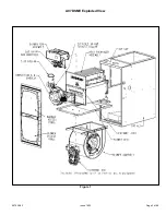
Page 3: ...507029 03 Page 3 of 68 Issue 1622 A97DSMV Exploded View Figure 1...
Page 13: ...507029 03 Page 13 of 68 Issue 1622 OUTDOOR TERMINATION KITS USAGE Table 3...
Page 24: ...507029 03 Page 24 of 68 Issue 1622 Figure 29...
Page 27: ...507029 03 Page 27 of 68 Issue 1622 Figure 36 Trap Drain Assembly Using 1 2 PVC or 3 4 PVC...
Page 33: ...507029 03 Page 33 of 68 Issue 1622 Figure 43 Typical A97DSMV Wiring Diagram...
Page 34: ...507029 03 Page 34 of 68 Issue 1622 Figure 45...
Page 35: ...507029 03 Page 35 of 68 Issue 1622 Figure 46...
Page 36: ...507029 03 Page 36 of 68 Issue 1622 Figure 47 Integrated Control...
Page 40: ...507029 03 Page 40 of 68 Issue 1622 Low Voltage Field Wiring Table 14 Single Stage 2 Stage...
Page 44: ...507029 03 Page 44 of 68 Issue 1622 BLOWER DATA...
Page 57: ...507029 03 Page 57 of 68 Issue 1622...
Page 58: ...507029 03 Page 58 of 68 Issue 1622...
Page 59: ...507029 03 Page 59 of 68 Issue 1622...
Page 60: ...507029 03 Page 60 of 68 Issue 1622 Configuring Unit Size Codes...
Page 61: ...507029 03 Page 61 of 68 Issue 1622 Troubleshooting Heating Sequence of Operation...
Page 62: ...507029 03 Page 62 of 68 Issue 1622 Troubleshooting Heating Sequence of Operation continued...
Page 63: ...507029 03 Page 63 of 68 Issue 1622 Troubleshooting Heating Sequence of Operation continued...
Page 64: ...507029 03 Page 64 of 68 Issue 1622 Troubleshooting Heating Sequence of Operation continued...
Page 65: ...507029 03 Page 65 of 68 Issue 1622 Troubleshooting Cooling Sequence of Operation...
Page 66: ...507029 03 Page 66 of 68 Issue 1622 Troubleshooting Continuous Fan Sequence of Operation...


