


Instruction
handbook
- Use
ARMANNI
4.3
Drives and signals
4.3.1
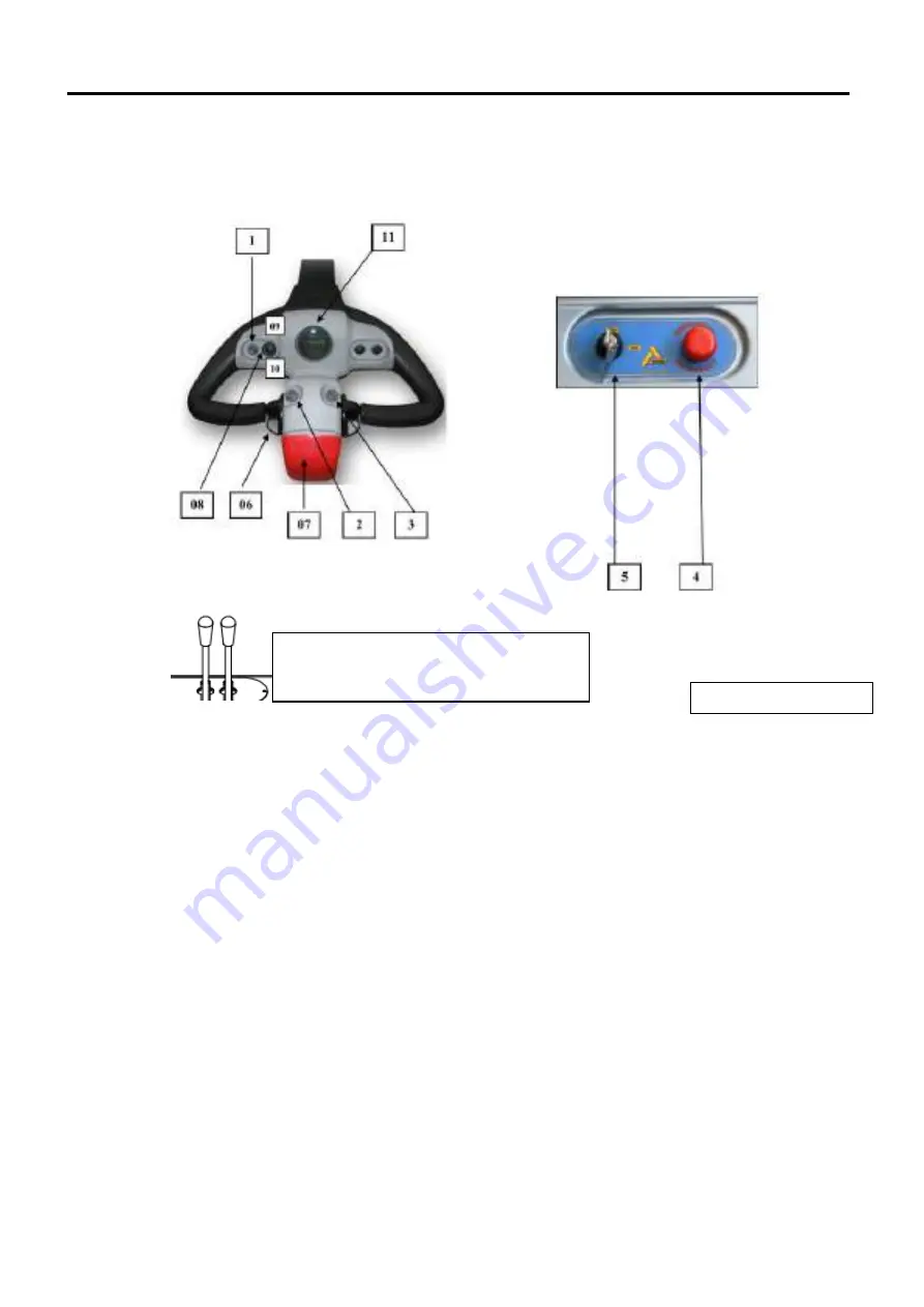
Drives
The drives for the truck working are both on the driving steering wheel and on the instrument
board, as you see in Fig. 4.2
Their functions are described as follows in position order:
01: Audible signal push-button: by pressing it, it closes a circuit that gives voltage to an electric
horn that produces the sound; by releasing it, the sound is interrupted and returns to the
initial position.
02/03: Lifting and lowering push buttons; pull for lift or lower the forks;
04:
Emergency button. The button is provided with a mechanical locking system that, after being
activated, will retain the red mushroom-head button in the stop position (pressed button
position). If you press the button downwards, the current will be interrupted for the entire
system.
NOTE: For the normal operation of the truck, the emergency button must be in the released
position; to release the button, pull the red mushroom-head activation button upwards.
05: Key switch: it is the machine ignition switch; it is activated by introducing the key and
carrying out a slight rotation clockwise, at the same time the 05 pilot light will light up.
06: Butterfly control device: this device controls the onward-backward running of the truck; the
devices are two, one for each handgrip (right and left) and work at the same time (when one
rotates, automatically the other one rotates as well, since they are connected by a spindle).
It works as follows:
-
By gripping the knob, rotating onwards the butterfly device with the thumb and
operating on the tongues it is possible to obtain an accelerated movement onwards of
the truck; by releasing the thumb from the tongues, the truck returns to the initial
position with a constant deceleration. When the deceleration is over
,
the stop force of
the electrobrake damps the inertial force acquired by the truck weight and stops
it.
4-2
Fig. 4.2 Panel control
Optionals:
-
Lifting and lowering lever
-Optional lever
Summary of Contents for CP LIGHT evo 030
Page 1: ...FORKLIFT CP LIGHTevo030 con PINZA BECCO...
Page 2: ......
Page 42: ......
Page 43: ......


