background image

19

Assembling Instructions

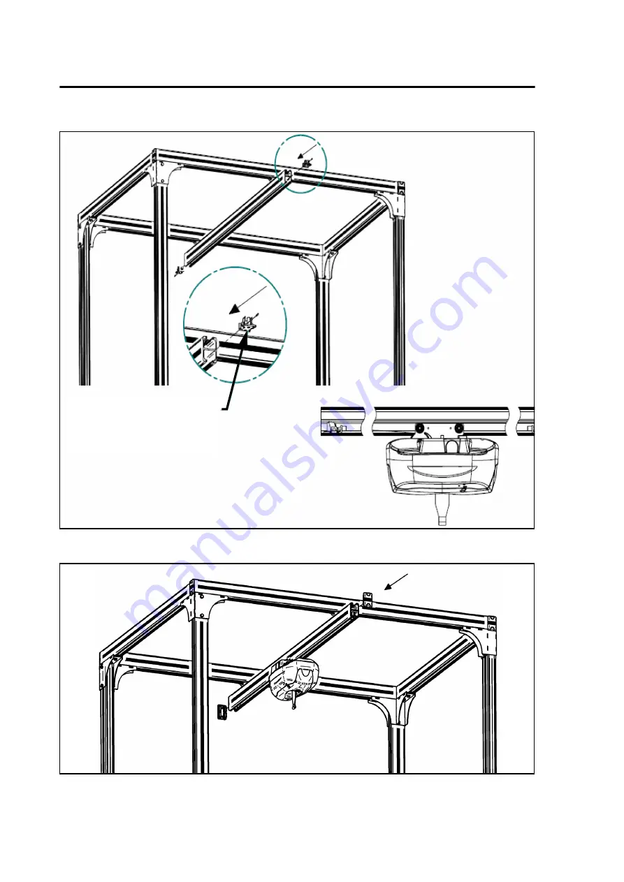
 Fig. 19

 Fig. 20

RAIL STOPPER 

(INSERT THE TRACK LIFT BEFORE 

INSTALLING THE SECOND RAIL 

STOPPER)

Summary of Contents for KWIKtrak

Page 1: ...KWIKtrak 4 Post Semi Permanent Rack Assembly Assembling Instructions 001 11950 EN rev 2 December 2011 ...

Page 2: ...joHuntleigh group of companies ArjoHuntleigh 2011 As our policy is one of continuous improvement we reserve the right to modify designs without prior notice The content of this publication may not be copied either whole or in part without the consent of ArjoHuntleigh ...

Page 3: ...anual 5 Intended Use 5 Verifying the Package Contents upon Receipt 5 How to Use this Manual 5 Safety Instructions 6 Safety Instructions and Warnings 6 Part Designation 7 Semi Permanent Rack System 7 Required Tools 8 Assembling Instructions 9 Assembling the 4 Post Rack 9 Specifications 20 Table of Contents ...

Page 4: ...cation to its products Service and Support If you require further information please contact your local ArjoHuntleigh representative who can offer comprehensive support and service programs to maximize the long term reliability safety and value of the product You could also contact your local ArjoHuntleigh representative for replacement parts Your service representative stocks the parts you will n...

Page 5: ... to ensure it is complete and inspect the equipment for possible damage due to shipping If there is any damage DO NOT USE the equipment WARNING CAUTION NOTE and notify the carrier immediately to file a claim Provide complete information concerning damage claims or shipping errors to your local ArjoHuntleigh representative Include all equipment identification numbers and group part numbers if any a...

Page 6: ...onents are present see table on page 7 Follow the assembly procedure sequence Use each and every one of the parts DO NOT leave any out This equipment must be used by a caregiver with proper training to work with the patient to be transferred When performing a transfer do not allow the patient to swing on the rack WARNING The maximum track length for this system is determined by the lift in use as ...

Page 7: ...el track X 2 4 Parallel track Y 2 5 Autolock end stoppers 6 6 XY trolley 1 7 Mobile track X 1 8 Plastic end cap 6 10 or 12 according to model Plastic end cap halves for kit including H140 rails 2 or 6 according to model 9 Adjustable levelling feet 4 10 Hex bolt with lockwasher plastic cap 8 Part Designation ...

Page 8: ... mm hexagonal key 6 mm Allen key Bubble level 8 mm Allen key TROLLEY FOR PORTABLE LIFT 700 10650 OR CHARGER INTERFACE FOR FIXED CEILING LIFT 700 15510 NOTE Installation instructions for the charger interface for fixed ceiling lifts are included with the Charger Interface Kit ...

Page 9: ...ts Verify that the lockwashers are installed at their proper place as shown Fig 4 2 Fasten the corner bracket assembly to the top of each post Do so for all four posts Properly insert the two screws M10 x 75 HEX through the post and tighten to a torque of 20 N m 15 lbf ft Secure them with the corresponding locknuts using a 17 mm socket tool or hexagonal key Verify that the lockwashers are installe...

Page 10: ...t 000 03030 does not protrude into the inner cavity of the levelling feet before attempting to insert the posts Fig 5 4 Adjust the bottom part of the levelling feet so that there is about 10 mm 3 8 in play Insert each post within its corresponding levelling foot Fig 6 M6 x 10 HC screws Screws must not protrude into inner cavity when post is inserted 10 mm 3 8 in ...

Page 11: ...he installation safer by greatly reducing the risk of the mobile track shifting from its position in the event that the end of the track should be subjected to a violent impact prevent the possibility of the installed track lift from falling from either end of the mobile track Look carefully for information concerning the various installation locations for end stoppers in the following assembly in...

Page 12: ...racks are properly inserted on the correct side see Fig 8 Fig 8 6 Choose two of the four fixed track sections that will hold the trolleys for the mobile track see Fig 2 item 4 7 Slide the individual XY kit trolleys and end stoppers into both of the selected fixed track sections see Fig 9 Fig 9 ...

Page 13: ...areful not to allow the trolleys for the mobile track or the end stoppers to fall out Fig 10 9 Make sure that the fixed track are positioned flush with the outer edges of the corner bracket of the top post assembly see Fig 11 Fig 11 10 Secure the assembly by firmly tightening the four screws M12 x 30 low head socket screws located on the bottom of each of the corner brackets see Fig 12 ...

Page 14: ...from the ground while the other adjusts the level by rotating the bottom of the levelling feet until the horizontal track is perfectly horizontal 16 Move the bubble level to the next horizontal track and repeat previous steps until the entire rack is perfectly levelled CAUTION Make sure that the lockwashers are installed at the proper locations ALLEN KEY 8MM NOTE Levelling the assembly must be per...

Page 15: ...obile track that allows the lift to move within the area spanned by the 4 Post system Once all four fixed tracks are joined to their corresponding posts 17 Slide the mobile track onto the wheeled trolleys suspended under the parallel fixed tracks Be sure to include the end stoppers that came wrapped with the XY trolley kit in the right sequence and direction see Fig 13 and Fig 14 Fig 13 ...

Page 16: ...uctions Fig 14 Once the mobile track is in place 18 Straighten the track so that it is squared to the fixed tracks 19 Tighten the setscrews on the trolleys with a 5 mm Allen key see Fig 15 Fig 15 End stoppers BOTH PLACES ...

Page 17: ...d contact the end stoppers of the fixed track evenly If not loosen the setscrews readjust the mobile track and retighten the setscrews see Fig 15 21 Slide the autolock end stoppers on the mobile track to a distance of 25 mm 1 in from each of the XY trolleys see Fig 16 22 Tighten the setscrews on the end stoppers using a 6 mm Allen key see Fig 17 Fig 16 Fig 17 2 5 mm 1 in Detail B B ...

Page 18: ...stopper to the track Insert the end stopper into the track and test the end stopper by trying to push it back out of the track The stopper should not be able to move Firmly tighten the setscrews using a 6 mm Allen key The end stopper is now installed Slide the lift or portable trolley into the mobile track see Fig 19 24 Insert the second stopper into the mobile track Secure the end stopper accordi...

Page 19: ...19 Assembling Instructions Fig 19 Fig 20 RAIL STOPPER INSERT THE TRACK LIFT BEFORE INSTALLING THE SECOND RAIL STOPPER ...

Page 20: ...80 mm 2067 mm min 81 3 8 in KWIKtrak 180 mm PRODUCT CODIFICATION A B 9 9 0 X X X X 30 3 0 m 10 ft 35 3 5 m 11 ft 6 in 40 4 0 m 13 ft 45 4 5 m 14 ft 9 in 30 3 0 m 10 ft 35 3 5 m 11 ft 6 in 40 4 0 m 13 ft 45 4 5 m 14 ft 9 in Specifications ...

Page 21: ...UK BEDFORDSHIRE LU1 1TD Tel 44 1582 745800 Fax 44 1582 745866 E mail international arjohuntleigh com ITALIA ArjoHuntleigh S p A Via di Tor Vergata 432 00133 ROMA ITALIA Tel 39 0 6 87426211 Fax 39 0 6 87426222 E mail Italy promo arjohuntleigh com NEDERLAND ArjoHuntleigh Nederland BV Biezenwei 21 4004 MB TIEL Postbus 6116 4000 HC TIEL Tel 31 0 344 64 08 00 Fax 31 0 344 64 08 85 E mail info nl arjohu...

Page 22: ...ArjoHuntleigh GETINGE and MAQUET ArjoHuntleigh focuses on patient mobility and wound management solutions GETINGE provides solutions for infection control within healthcare and contamination prevention within life sciences MAQUET specializes in solutions therapies and products for surgical interventions and intensive care www ArjoHuntleigh com ArjoHuntleigh AB Verkstadsvägen 5 241 38 Eslöv SWEDEN ...

Reviews: