Arista DCS-7020TR-48 Quick Start Manual Download Page 40

36

Quick Start Guide: 7000 Series 1 RU-Gen 3 Data Center Switches

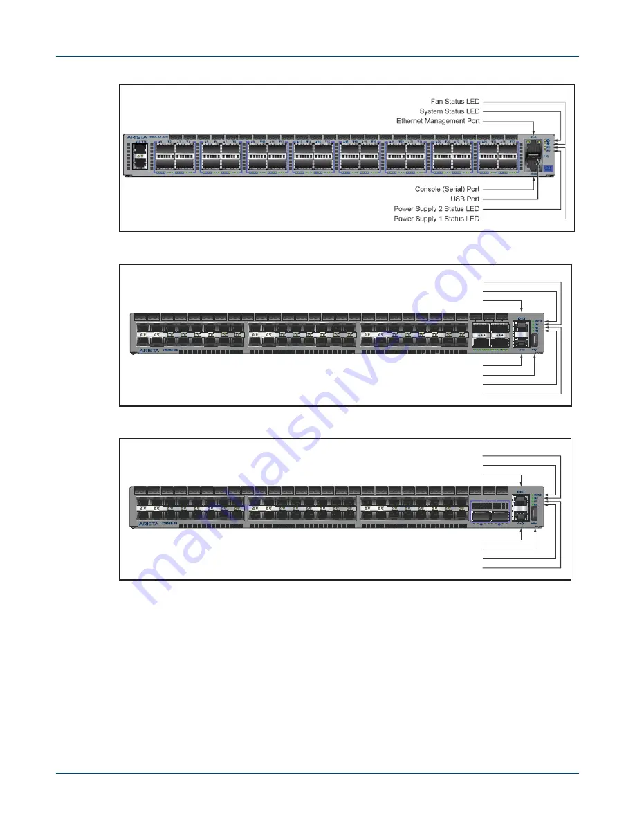
Appendix C: Front Panel

Figure C-9: DCS-7060CX-32S

Figure C-10: DCS-7280SE-64

Figure C-11: DCS-7280SE-68

49

50

51

52

11

15

13

9

7

5

3

1

12

16

14

10

8

6

4

2

43

47

45

41

39

37

35

33

44

48

46

42

40

38

36

34

27

31

29

25

23

21

19

17

28

32

30

26

24

22

20

18

System Status LED

Fan Status LED

Power Supply 2 Status LED
Power Supply 1 Status LED

USB Port

Ethernet Management Port

Console (Serial) Port

Summary of Contents for DCS-7020TR-48

Page 1: ...Quick Start Guide 7000 Series 1 RU Gen 3 Data Center Switches Arista Networks www arista com PDOC 00041 13 ...

Page 2: ...Networks and the Arista logo are trademarks of Arista Networks Inc in the United States and other countries Other product or service names may be trademarks or service marks of others Headquarters 5453 Great America Parkway Santa Clara CA 95054 USA 408 547 5500 www arista com Support 408 547 5502 866 476 0000 support arista com Sales 408 547 5501 866 497 0000 sales arista com ...

Page 3: ...ries that may be packaged in the same box as the main unit Inspect the packing list and confirm that you received all listed items Compare the packing list with your purchase order Appendix B provides a list of components included with the switch 1 3 Installation Process The following tasks are required to install and use the switch Step 1 Select and prepare the installation site Section 2 1 Step ...

Page 4: ...e 1 et pour assurer que la classe 1 AEL limite d émission admissible par EN IEC 6 825 CSA E60825 1 et Code des règlements fédéraux 21 CFR 1040 ne soit pas dépassée après avoir installé l émetteur récepteur de laser Ne pas installer des appareils à laser dont la cote de classe est supérieure à 1 Voir toutes les consignes de sécurité qui ont accompagné l émetteur récepteur avant l installation Seuls...

Page 5: ...t Guide 7000 Series 1 RU Gen 3 Data Center Switches 3 Important No user serviceable parts inside Refer all servicing to qualified service personnel Aucune pièce réparable par l utilisateur à l intérieur Confiez toute réparation à un technicien qualifié ...

Page 6: ...19 x 1 75 x 16 inches 44 5 x 4 4 x 40 6 cm 19 x 1 75 x 16 inches 44 5 x 4 4 x 40 6 cm 19 x 1 75 x 16 inches 44 5 x 4 4 x 40 6 cm 19 x 1 75 x 16 inches 44 5 x 4 4 x 40 6 cm 19 x 1 75 x 16 inches 44 5 x 4 4 x 52 3 cm 19 x 1 75 x 20 6 inches 44 5 x 4 4 x 40 6 cm 19 x 1 75 x 16 inches 44 5 x 4 4 x 40 6 cm 19 x 1 75 x 16 inches 44 5 x 4 4 x 40 6 cm 19 x 1 75 x 16 inches 44 5 x 4 4 x 52 3 cm 19 x 1 75 x...

Page 7: ...VDC 15 A 48 to 60 VDC 24 A Power Draw Typical Maximum DCS 7050QX 32S DCS 7050SX 64 DCS 7050SX 72 DCS 7050SX 96 DCS 7050TX 48 DCS 7050TX 64 DCS 7050TX 72 DCS 7050TX 96 DCS 7280SE 64 DCS 7280SE 68 DCS 7280SE 72 DCS 7280QR C36 DCS 7050SX 72Q DCS 7280SR 48C6 DCS 7280TR 48C6 DCS 7060CX 32S DCS 7050QX2 32S DCS 7050SX2 72Q DCS 7050TX 72Q DCS 7160 32CQ DCS 7160 48YC6 DCS 7160 48TC6 DCS 7280SR2 48YC6 DCS 7...

Page 8: ...6 Quick Start Guide 7000 Series 1 RU Gen 3 Data Center Switches Specifications Overview ...

Page 9: ...rear panel Their red handles indicate that they are air exit modules Verify that each module has the same airflow direction Base the switch orientation on the airflow direction of the modules to assure the air inlet is always oriented toward the cool aisle Air Exit modules orient the rear panel toward the hot aisle Air Inlet modules orient the rear panel toward the cool aisle If the airflow direct...

Page 10: ...nel indicators can be easily read Power cords can reach from the power outlet to the connector on the rear panel Important All power connections must be removed to de energize the unit Toutes les connexions d alimentation doivent être enlevées pour hors tension l appareil 2 2 Tools and Parts Required for Installation Each switch provides an accessory kit that contains parts that are required to in...

Page 11: ... Assemble or disassemble equipment only in a static free work area Use a conductive work surface such as an anti static mat to dissipate static charge Wear a conductive wrist strap to dissipate static charge accumulation Minimize handling of assemblies and components Keep replacement parts in their original static free packaging Remove all plastic foam vinyl paper and other static generating mater...

Page 12: ...8 Quick Start Guide 7000 Series 1 RU Gen 3 Data Center Switches Electrostatic Discharge ESD Precautions Chapter 2 Preparation ...

Page 13: ...unt the switch onto a two post rack assemble the mounting brackets to the chassis then attach the brackets to the rack posts Two post accessory kits include the following two post mounting parts 2 three hole mounting brackets Each chassis side has attachment pins that align with bracket holes Pin orientation is symmetric and equidistant supporting bracket placements where the flange is flush with ...

Page 14: ...y openings Figure 3 1 Bracket Mount Examples for Two Post Rack Mount Figure 3 2 Improper Bracket Mount Examples for Two Post Rack Mount Step 3 Slide the bracket toward the front flange until the bracket clip locks with an audible click Figure 3 3 Attaching the Mounting Brackets to the Switch Chassis To remove the mounting bracket from the chassis lift the front edge of the mounting bracket clip wi...

Page 15: ...k This procedure attaches the switch to the rack Figure 3 4 Step 1 Lift the chassis into the rack Position the flanges against the rack posts Step 2 Select mounting screws that fit your equipment rack Step 3 Attach the bracket flanges to the rack posts Figure 3 4 Inserting the Switch into the Rack After completing the two post rack mount proceed to Chapter 4 ...

Page 16: ...ket holes Pin orientation is symmetric and equidistant supporting bracket placements where the flange is flush with the front switch panel flush with the rear panel or not flush with either panel Each bracket hole includes a key opening for placing the bracket flush with the chassis and then locking it into place Important Attachment pins must engage at least five of the six bracket holes Goupille...

Page 17: ...h chassis as depicted by Figure 3 7 Step 1 Align the mounting brackets with the attachment pins to obtain the desired mounting position Step 2 Place the bracket flush on the chassis with attachment pins protruding through key openings Step 3 Slide the bracket toward the front flange until the bracket clip locks with an audible click To remove the mounting bracket from the chassis lift the front ed...

Page 18: ... into a rack by inserting the plugs into rack slots When installing rails into posts with threaded or rounded holes remove all plugs located on both sides of the assembled rails then install the rails with bolts that fit the rack Figure 3 8 Attaching the Mounting Brackets to the Switch Chassis This procedure attaches the rails to a four post rack Step 1 Slide a rail rod into a rail slide Figure 3 ...

Page 19: ...ht posts relative to the left rack posts If the rack plugs were previously removed use bolts to attach the rail to the rack Step 3 Attach the slide end of the rail to the front post by extending the rail end past the post then contracting the rail while guiding the rack plugs into the post Figure 3 10 Inset B Step 4 Repeat step 1 through step 3 for the left posts Ensure the rails are on the same h...

Page 20: ... the switch into the rack and insert the mounting brackets into the slide rails Figure 3 11 Inserting the Switch onto the Rails Step 2 Slide the switch on the rails toward the rear posts until the mounting bracket flanges are flush with the rail flanges attached to the rack posts Step 3 Attach the bracket flanges to the rack post using the quick release thumb screws supplied with the brackets Figu...

Page 21: ...re size should meet local and national installation requirements Commercially available 6 AWG wire is recommended for installations in the U S À la terre et de mise à la terre fils cosses M4 x 0 7 ne sont pas fournis Calibre des fils doit satisfaire des exigences de l installation locale et nationale Disponible dans le commerce 6 fils AWG est recommandé pour les installations aux États Unis Figure...

Page 22: ...ead all installation instructions before connecting the system to the power source Lire toutes les instructions d installation avant de brancher le système à la source d alimentation Non Redundant Configuration Connect power to either of the two power supplies Redundant Power Supply Configuration Connect power to both power supplies Power down the Switch Remove all power cords and wires from the p...

Page 23: ...evice circuit breakers or fuses on DC power lines servicing the circuits Turn off the power line circuits or remove the fuses Pouvoir assurer qu il est retiré de circuits DC avant d effectuer des actions d installation Localiser les disjoncteurs ou des fusibles sur les lignes de courant continu desservant les circuits Coupez les circuits de lignes d alimentation ou retirer les fusibles Important W...

Page 24: ...ing lugs are not supplied Strip the wires to the appropriate length for the lugs The wires connecting the DC power supply to the power source must meet the following requirements DC Input Wire Size 4 6 AWG 21 2 mm2 to 13 3 mm2 Primary Ground Wire Size 4 6 AWG 21 2 mm2 to 13 3 mm2 per power supply The conductors are copper Step 3 Use agency approved compression pressure lugs for wiring terminations...

Page 25: ...ing the DC power supply to the power source meet the following DC Input Wire Size AWG 14 2 0 mm2 or larger as appropriate Safety Ground Wire Size AWG 14 2 0 mm2 or larger as appropriate Wire Terminal Lug ring or spade fork 14 16 AWG 8 4 mm screw Over current protection 20 A Important Ensure power is removed from DC circuits before performing any installation actions Locate circuit breakers or fuse...

Page 26: ...pper wire Calibre doit respecter les exigences locales et nationales et les codes de l électricité Utiliser seulement du fil de cuivre Step 3 Connect the DC input wires to the terminal block in this order 1 Ground cable to the ground connector on the face of the power supply 2 Negative source DC cable to the negative connector on the terminal block 3 Positive source DC cable to the positive connec...

Page 27: ...J 45 pin 8 CTS RJ 45 pins 2 DTR and RJ 45 pin 7 DSR are not electrically connected to anything For most models the front panel contains the console management and USB ports Figure 4 7 displays the ports on the front panel of the DCS 7050QX 32S switch Figure 4 8 displays the ports on rear panel of the DCS 7280SR 48C6 switch Appendix C and Appendix D display the front and rear panels of all switches...

Page 28: ...B 9 serial adapter cable The switch uses the following default settings 9600 baud No flow control 1 stop bit No parity bits 8 data bits Ethernet Management Port Connect to 10 100 1000 management network with RJ 45 Ethernet cable USB Port The USB port may be used for software or configuration updates Caution Excessive bending can damage interface cables especially optical cables Flexion excessive p...

Page 29: ... a default route to a network gateway Step 1 Provide power to the switch Section 4 1 Step 2 Connect the console port to a PC Section 4 2 As the switch boots without a startup config file it displays the following through the console The device is in Zero Touch Provisioning mode and is attempting to download the startup config from a remote system The device will not be fully functional until eithe...

Page 30: ... IP address 192 0 2 8 24 in this example to an Ethernet management port localhost config interface management 1 localhost config if Ma1 1 ip address 192 0 2 8 24 Step 10 Save the configuration by typing write memory or copy running config startup config localhost copy running config startup config When the management port IP address is configured use this command to access the switch from a host u...

Page 31: ...ors A 1 1 Switch Indicators Front panel LEDs are located on the right side of the chassis and display system fan and power supply status Figure A 1 displays the DCS 7050QX 32S front panel LEDs Figure A 1 System Status Indicators System Status LED Fan Status LED Power Supply 1 Status LED Power Supply 2 Status LED ...

Page 32: ...ctive Amber Two or more fans any combination of fan modules or PSU fans are disconnected or malfunctioning The switch will automatically execute a graceful shutdown shortly Fan Status LED Green All fan and power modules are operating normally Amber Single fan module is removed or malfunctioning It is also amber when a PSU is completely removed or has a stuck fan rotor Red Two or more fans any comb...

Page 33: ...fan status LED states The AC Power Supply Status LEDs are on the power supply modules as displayed in Figure A 4 Figure A 4 AC Power Supply Status LED Yellow Port is software disabled Flashing Yellow Port failed diagnostics Table A 2 Port LED States Front Continued LED State Status Table A 3 Fan Status LED States Rear LED State Status Off The fan module is not detected If it is inserted it may not...

Page 34: ... the show environment commands Table A 4 AC Power Supply Status LED States Rear Power Supply State PWR 500AC F PWR 500AC R PWR 745AC F PWR 745AC R PWR 747AC F PWR 747AC R Input power present Normal operation Green Green Green Input power present Power Supply fault Yellow Yellow Yellow No Input power Supply installed in chassis Off Off Off Input power present Supply not installed in chassis Green G...

Page 35: ...ccessory kit that contains parts that are required to install the switch This appendix lists the installation parts contained in the switch accessory kit B 1 Rack Mount Parts B 1 1 Four Post Rack Mount Parts Figure B 1 Four Post Rack Mount Parts B 1 2 Two Post Rack Mount Parts Figure B 2 Two Post Rack Mount Parts ...

Page 36: ...ta Center Switches Cables Appendix B Parts List B 2 Cables Warning All provided power cables are for use only with Arista products Quantity Description 2 Power cables IEC 320 C13 C14 13 A 250 V 1 RJ 45 Patch Panel Cable 1 RJ 45 to DB9 Adapter Cable ...

Page 37: ... 36 25 26 27 28 21 22 23 24 17 18 19 20 13 14 15 16 9 10 11 12 System Status LED Fan Status LED Power Supply 2 Status LED Power Supply 1 Status LED USB Port Ethernet Management Port Console Serial Port 11 27 43 15 31 47 13 29 45 9 25 41 7 23 39 5 21 37 3 19 35 1 17 33 12 28 44 16 32 48 14 30 46 10 26 42 8 24 40 6 22 38 4 20 36 2 18 34 System Status LED Fan Status LED Power Supply 2 Status LED Powe...

Page 38: ... Port Console Serial Port System Status LED Fan Status LED 11 15 13 9 7 5 3 1 12 16 14 10 8 6 4 2 43 47 45 41 39 37 35 33 44 48 46 42 40 38 36 34 27 31 29 25 23 21 19 17 28 32 30 26 24 22 20 18 7050SX 96 Power Supply 1 Status LED Power Supply 2 Status LED USB Port Ethernet Management Port Console Serial Port System Status LED Fan Status LED 1 2 3 4 5 6 7 8 9 10 11 12 13 14 15 16 33 34 35 36 17 18 ...

Page 39: ...onsole Serial Port 7050TX 72 1 2 3 4 5 6 7 8 9 10 11 12 13 14 15 16 17 19 20 21 22 23 24 25 26 27 28 29 30 31 32 33 34 36 37 38 39 40 41 42 43 44 45 46 47 48 Power Supply 1 Status LED Power Supply 2 Status LED USB Port Ethernet Management Port Console Serial Port System Status LED Fan Status LED 7050TX 96 1 2 3 4 5 6 7 8 9 10 11 12 13 14 15 16 17 18 19 20 21 22 23 24 25 26 27 28 29 30 31 32 33 34 ...

Page 40: ...34 27 31 29 25 23 21 19 17 28 32 30 26 24 22 20 18 System Status LED Fan Status LED Power Supply 2 Status LED Power Supply 1 Status LED USB Port Ethernet Management Port Console Serial Port 11 15 13 9 7 5 3 1 12 16 14 10 8 6 4 2 43 47 45 41 39 37 35 33 44 48 46 42 40 38 36 34 27 31 29 25 23 21 19 17 28 32 30 26 24 22 20 18 System Status LED Fan Status LED Power Supply 2 Status LED Power Supply 1 S...

Page 41: ...X2 32S Figure C 14 DCS 7280SR 48C6 Figure C 15 DCS 7280TR 48C6 11 15 13 9 7 5 3 1 12 16 14 10 8 6 4 2 43 47 45 41 39 37 35 33 44 48 46 42 40 38 36 34 27 31 29 25 23 21 19 17 28 32 30 26 24 22 20 18 Power Supply 1 Status LED Power Supply 2 Status LED USB Port Ethernet Management Port Console Serial Port System Status LED Fan Status LED ...

Page 42: ...38 Quick Start Guide 7000 Series 1 RU Gen 3 Data Center Switches Appendix C Front Panel Figure C 16 DCS 7280QR C36 Figure C 17 DCS 7050SX 72Q Figure C 18 DCS 7050SX2 72Q ...

Page 43: ...tart Guide 7000 Series 1 RU Gen 3 Data Center Switches 39 Figure C 19 DCS 7050TX 72Q Figure C 20 DCS 7160 32CQ Figure C 21 DCS 7160 48YC6 System Status LED Fan Status LED Power Supply 2 Status LED Power Supply 1 Status LED USB Port ...

Page 44: ...CS 7280SR2A 48YC6 molex molex molex molex molex molex molex molex molex molex molex molex 1 2 3 4 5 6 7 8 9 10 11 12 13 14 15 16 17 18 19 20 21 22 23 24 25 26 27 28 29 30 31 32 33 34 35 36 37 38 39 40 41 42 43 44 45 46 47 48 49 50 51 52 53 54 1 QSFP 100G 7160 48TC6 System Status LED Fan Status LED Power Supply 2 Status LED Power Supply 1 Status LED USB Port ...

Page 45: ...Appendix C Front Panel Quick Start Guide 7000 Series 1 RU Gen 3 Data Center Switches 41 Figure C 25 DCS 7020TR 48 Figure C 26 DCS 7280SRA 48C6 Figure C 27 DCS 7060CX2 32S ...

Page 46: ...42 Quick Start Guide 7000 Series 1 RU Gen 3 Data Center Switches Appendix C Front Panel Figure C 28 DCS 7280TRA 48C6 Figure C 29 DCS 7280QRA C36S ...

Page 47: ...RESS IIIIIIIIIIIIIIIIIIIIIIIIIIIIIIIIIII SERIAL NUMBER IIIIIIIIIIIIIIIIIIIIIIIIIIIIIIIIIII ASSEMBLY NUMBER IIIIIIIIIIIIIIIIIIIIIIIIIIIIIIIIIII Earth Grounding Pad Power Supply Module 1 Power Supply Module 2 Fan Module 1 Handle Fan Module 2 Handle Fan Module 3 Handle Fan Module 4 Handle 3 SN JPE0000000 2 ASASY 90528 02 01 A S A S Y 9 0 5 2 8 0 2 0 1 1 PS2 4 MAC 00 00 00 00 00 00 PS1 Console Serial ...

Page 48: ...44 Quick Start Guide 7000 Series 1 RU Gen 3 Data Center Switches Appendix D Rear Panel ...

Page 49: ...er RMN Product Number s AN1501 DCS 7050SX 72Q DCS 7050SX2 72Q AN1502 DCS 7050TX 72Q AN1504 DCS 7280SR 48C6 AN1506 DCS 7280TR 48C6 AN1508 DCS 7280QR C36 AN1510 DCS 7280CR 48 AN1511 DCS 7160 32CQ AN1604 DCS 7280QRA C36S DCS 7280QR C36S AN1606 DCS 7020TRA 48 AN1607 DCS 7020SRA 48C6 AN1608 DCS 7020TRA 48C6 AN1611 DCS 7160 48T6 AN1612 DCS 7160 48YC6 AN1615 DCS 7280SR2A 48YC6 AN1616 DCS 7280QR C72 DCS 7...

Page 50: ... 7280SRM 48C6 AN1624 DCS 7280SR 24C2 AN1626 DCS 7280SRM 40CX2 AN1701 DCS 7280SRL 48C6 AN1703 DCS 7050SX3 48YC6 AN1704 DCS 7060SX3 48YC12 AN1705 DCS 7050CX3 32S AN1706 DCS 7280SR 32C2 AN1707 DCS 7170 32C Table E 1 Regulatory Model Numbers and Product Numbers Continued Regulatory Model Number RMN Product Number s ...

Page 51: ... Gen 3 Data Center Switches 47 Appendix F Taiwan RoHS Information This appendix provides Taiwan RoHS information for switches covered by this guide For Taiwan BSMI RoHS Table go to https www arista com assets data pdf AristaBSMIRoHS pdf ...

Page 52: ...48 Quick Start Guide 7000 Series 1 RU Gen 3 Data Center Switches Appendix F Taiwan RoHS Information ...

Reviews: