background image

31

When I install my display what should I do if the screen shows ‘Cannot display this 
video mode’?

Recommended video mode is 1920x1200 @60Hz.
1.   Unplug all cables, then connect your PC to the display that you used previously.
2.   In the Windows Start Menu, select Settings/Control Panel. In the Control Panel Window, select the 

Display icon. Inside the Display Control Panel, select the ‘Settings’ tab. Under the setting tab, in 
box labeled ‘desktop area’, move the slidebar to 1920x1200 pixels.

3.  Open ‘Advanced Properties’ and set the Refresh Rate to 60Hz, then click OK.
4.  Restart your computer and repeat step 2 and 3 to verify that your PC is set at 1920x1200@60Hz.
5.  Shut down your computer, disconnect your old display and reconnect your Arista LCD display.
6.  Turn on your display and then turn on your PC.

What does ‘refresh rate’ mean in connection with an LCD display?

The refresh rate is of much less relevance for LCD displays. LCD displays display a stable, 

fl

 icker-free 

image at 60Hz. There is no visible difference between 85Hz and 60Hz.

Will the LCD screen be resistant to scratches?

A protective coating is applied to the surface of the LCD, which is durable to a certain extent 
(approximately up to the hardness of a 2H pencil). In general, it is recommended that the panel surface 
is not subject to any excessive shocks or scratches. An optional protective cover with greater scratch 
resistance is also available.

How should I clean the LCD surface?

For normal cleaning, use a clean, soft cloth. For extensive cleaning, please use isopropyl alcohol. Do 
not use other solvents such as ethyl alcohol, ethanol, acetone, hexane, etc.

Can I connect my LCD display to any PC, workstation or Mac?

Yes. All LCD displays are fully compatible with standard PCs, Macs and workstations. You may need a 
cable adapter to connect the display to your Mac system. Please contact your dealer/retailer for more 
information.

Are LCD display Plug-and-Play?

Yes, the displays are Plug-and-Play compatible with WindowsXP, 7,windows 8 

What is a Liquid Crystal Display?

A Liquid Crystal Display (LCD) is an optical device that is commonly used to display ASCII characters 
and images on digital items such as watches, calculators, portable game consoles, etc. LCD is the 
technology used for displays in notebooks and other small computers. Like light-emitting diode and 
gas-plasma technologies, LCD allows displays to be much thinner than cathode ray tube (CRT) 
technology. LCD consumes much less power than LED and gas-displays because it works on the 
principle of blocking light rather than emitting it.

What is polarization ?

Polarization is basically directing light to shine in one direction. Light is electromagnetic waves. Electric 
and magnetic 

fi

 elds oscillate in a direction perpendicular to the propagation of the light beam. The 

direction of these 

fi

 elds is called the 'polarization direction'. Normal or non-polarized light has 

fi

 elds in 

several directions; polarized light has a 

fi

 eld in only one direction.

What kind of wide-angle technology is available? How does it work?

The TFT LCD panel is an element that controls/displays the inlet of a backlight using the dual-
refraction of a liquid crystal. Using the property that the projection of inlet light refracts toward the major 
axis of the liquid element, it controls the direction of inlet light and displays it. Since the refraction ratio 
of inlet light on liquid crystal varies with the inlet angle of the light, the viewing angle of a TFT is much 
narrower than that of a CDT. Usually, the viewing angle refers to the point where the contrast ration 
is 10. Many ways to widen the viewing angle are currently being developed and the most common 
approach is to use a wide viewing angle 

fi

 lm, which widens the viewing angle by varying the refraction 

ratio. IPS (In Plane Switching) or MVA (Multi Vertical Aligned) is also used to give a wider viewing 
angle. 

Frequently asked questions

Summary of Contents for ADM-1800 Series

Page 1: ...t you will be pleased with the performance and reliability of your new display The display was designed to meet the screen performance requirements of today s demanding industrial applications While complying with a wide variety of industrial video formats it delivers a larger screen area higher resolutions and greater color accuracy than many displays in its price range Version 1 3 ...

Page 2: ......

Page 3: ...h connector description 16 Installing 17 1 Panel mounting 17 2 Cutout size 17 Connecting the display 18 1 Connect the display via VGA or DVI 18 2 Connect the display via USB cable or RS 232 cable 19 3 Connect power adapter and cable 19 Installing calibration software 20 Video alignment or calibration 21 Operations 22 Picture setting 23 Option setting 24 Input source 25 Maintenance and troubleshoot...

Page 4: ...ny way please contact the manufacturer or the nearest authorized repair service provider for a replacement The power supply cord is used as the main disconnect device Ensure that the socket outlet is easily accessible after installation Overloaded AC outlets and extension cords are dangerous So are frayed power cords and broken plugs They may result in a shock or fire hazard Call your service tech...

Page 5: ...enna Increase the separation between the equipment and receiver Connect the equipment into an outlet on a circuit different from that to which the receiver is connected Consult the dealer or an experienced radio TV technician for help Copyright 2001 The information contained in this user s manual and all accompanying documentation is copyrighted and all rights are reserved This publication may not...

Page 6: ...y and interface parameters via OSD OSD On Screen Display buttons on the rear panel Touch Screen Resistive Capacitive and SAW Option Easy plug and play DVI ensures true digital experience Embedded power supply eliminates external power adapters Applications The product covered herein are designed and manufactured for following application areas Office electronics Instrumentation and measuring equip...

Page 7: ...ended period of time it may leave an after image or ghost image on front of the screen This is a well known phenomenon that is caused by the shortcomings inherent in LCD technology In most cases the after image will disappear gradually over a period of time after the power has been switched off Be aware that the after image symptom cannot be repaired and is not covered under warranty Unpacking Unp...

Page 8: ... OSD settings or confirm some operations 3 Use for selecting options or increase the data 4 POWER Power On Off control 5 24V DC jack 24V DC power input 6 DVI jack DVI source input 7 VGA jack VGA source input 8 12V DC Input 12V DC power input 9 Touch connector RS232 Touch screen connector 10 Touch connector USB touch screen connector 10 ...

Page 9: ...8 8 4 Inch 10 10 4 Inch 12 12 1 Inch 15 15 Inch 17 17 Inch 18 18 5 Inch 19 19 Inch 20 20 1 Inch 21 21 5 Inch 24 24 Inch Options xxx 5 wire resistive touch screen Z xx No touch xx4 xx5 or Zx4 Zx5 Stainless steel bezel xx0 xx1 or Zx0 Zx1 Black color bezel xx0 xx4 or Zx0 Zx4 24VDC input xx1 xx5 or Zx1 Zx5 110 220VAC input Panel Mount ADM 1817AP 000 ADM 1817AP 001 ADM 1817AP Z00 ADM 1817AP Z01 Touch S...

Page 10: ...M 0 264 x 0 264 400 700 1200 1600 ADM 1812 12 1 Inch TFT 800 x 600 1024x768 16 7M 0 3075 x 0 3075 450 700 1300 1600 ADM 1815 15 0 Inch TFT 1024x768 16 7M 0 297 x 0 297 400 700 1200 1600 ADM 1817 17 0 Inch TFT 1820x1024 16 7M 0 264 x 0 264 350 1000 1600 1700 ADM 1818 18 5 Inch TFT 1366 x 768 16 7M 0 3 X 0 3 250 1000 1700 1600 ADM 1819 19 0 Inch TFT 1280 x 1024 16 7M 0 294 x 0 294 400 1000 1600 1700...

Page 11: ...maximum value 4 8V 5 0V 5 5V Note Before using the machine please make sure the pressure range of U disk temperature sensor and photosensitive sensor is enough LVDS signals output The minimum value The maximum value single LVDS screen 800x480 60Hz 1440x900 60Hz Dual LVDS screen 1280x1024 60Hz 1920x1080 60Hz VGA signals input VGA The minimum value The standard value The maximum value R 600mV 650mV ...

Page 12: ... 2 5 17 4 58 7 49 1 98 1 73 7 49 x5 68 4 4 Lbs ADM 1808 9 7 7 5 6 6 6 01 8 75 2 0 1 73 8 75 x6 6 6 6 Lbs ADM 1810 11 5 8 8 7 9 6 72 10 55 2 1 1 83 10 55 x7 9 7 0 Lbs ADM 1812 12 6 10 03 9 18 7 80 11 76 2 06 1 79 11 76 x9 18 8 8 Lbs ADM 1815 14 51 11 8 10 93 9 08 13 56 1 89 1 59 13 56 x10 93 11 1 Lbs ADM 1817 15 88 13 34 12 31 9 87 14 85 2 08 1 81 14 85 x12 31 14 Lbs ADM 1818 19 0 12 21 10 82 8 97 ...

Page 13: ...CD connectors plate which contains power port VGA port DVI port and Touch screen interface port There ports are described in further detail later Connectors located on the bottom of the chassis LCD Connector Plate Warning Make sure your display is grounded at all times Also make sure that it is on the same ground as any other equipment connected to its communications ports ...

Page 14: ...d 12 NC No connection 13 NC No connection 14 DVIVCC 5V power input 15 GND Ground 16 HPD Hot plug detect 17 RXD0 T M D S Data 0 18 RXD0 T M D S Data 0 19 GND T M D S Data 0 Shield 20 NC No connection 21 NC No connection 22 GND T M D S Clock Shield 23 RXDC T M D S Clock 24 RXDC T M D S Clock 25 NC No connection 26 NC No connection 27 NC No connection 28 NC No connection 29 NC No connection Pins in D...

Page 15: ...ion 5 GND Ground 6 GND Ground 7 GND Ground 8 GND Ground 9 NC No connection 10 GND Ground 11 NC No connection 12 TXD ISP program upgrade TXD signal serial transmit data 13 VGA HS VGA H Sync signal 14 VGA VS VGA V Sync signal 15 RXD ISP program upgrade RXD signal Serial receive data Pins in VGA signal input connector description 1 5 4 3 2 6 7 8 9 10 15 14 13 12 11 ...

Page 16: ... connection 2 TX ISP program upgrade TXD signal serial transmit data 3 RX ISP program upgrade RXD signal Serial receive data 4 NC No connection 5 GND Ground 6 NC No connection 7 NC No connection 8 NC No connection 9 NC No connection Pins in touch connector description 3 1 2 4 5 9 8 7 6 ...

Page 17: ... Tighten the bolt in the kits until the display panel is firmly secured to the control It is very important to locate the unit in a suitable environment Make sure the place has good ventilation is out of direct sunlight away from sources of excessive dust dirt heat water moisture and vibration Model Number Cutout WD x HD ADM 1806 7 49 x5 68 ADM 1808 8 75 x6 6 ADM 1810 10 55 x7 9 ADM 1812 11 76 x9 ...

Page 18: ...ector with that of the graphics adapter Connect DVI Digital Video Interface Cable Optional If you have a DVI digital graphics card adapter and a DVI cable connect it to the DVI IN connector of the display The optional DVI graphics adapter and the DVI cable can be ordered by contacting Aydin Displays Display rear panel VGA connector DVI connector VGA cable supplied DVI cable not supplied Signal flo...

Page 19: ... Connect the female end of the power cable to the AC power input receptacle on the AC DC adapter Then plug the male end of the power cable into an AC outlet Display rear panel DC Power cable supplied Display rear panel USB cable not supplied RS232 cable supplied Notes If you are using supplied cables accessories ensure they are correct for the model of panel and controller If you are making your o...

Page 20: ...ble click the setup to start to install the calibration software Installing calibration software 2 Click next to continue and go ahead following the dialog window 3 Restart the computer to finish the installing 4 Now the shortcuts of USB Controller can be found on the desktop ...

Page 21: ...as below Video alignment or calibration 2 Select the Tools of the eGalaxTouch screen and click the 4 Points Calibration then click OK for video calibration 3 Use the point of something such as the pen to calibrate the four points of the display 4 Once calibrated the touchscreen will be ready to use automatically each time the system is restarted ...

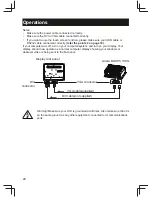
Page 22: ... computer was off turn on your computer system and turn on your display Your display should now operate as a normal computer display showing your windows or whatever video is being sent to the flat panel Display rear panel VGA connector DVI connector VGA cable supplied DVI cable not supplied Warning Make sure your LCD is grounded at all times Also make sure that it is on the same ground as any oth...

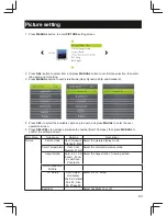
Page 23: ...wn and press MAUAL to enter the next operation screen 5 Press SEL SEL to decrease increase the number total 100 steps then press MANUAL to confirm the setting and exit Main Menu Sub menu Options Description Picture Picture mode User Dynamic Standard Mild Select the picture display mode Color Temperature User Cool Medium Warm Select the color temperature mode Aspect Ratio Auto 4 3 16 9 Zoom1 Zoom 2...

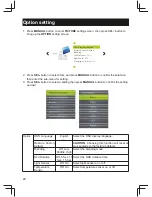
Page 24: ...enter the sub menu for setting 3 Press SEL button to select a setting then press MANUAL button to confirm the setting and exit Option OSD Language English Select the OSD display language Restore Factory Default CAUTION Choosing this function will reset all your settings to the factory s default Blending Off Low Middle High Select the blending mode Osd Duration Off 5 Sec 10 Sec 15 Sec Select the OS...

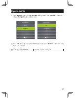
Page 25: ... PICTURE setting screen then press SEL button to bring up the Input Source setting screen 2 Press SEL button to select DVI PC RGB item then press MANUAL button to confirm the selection and exit Input Source DVI PC RGB Select the input source signal ...

Page 26: ...ance Regular maintenance of the ADM 1800 series industrial display can help prevent damage or downtime Warning Do not operate or service the unit with its chassis open There are hazardous voltages inside Service should only be performed by qualified and authorized personnel Make sure your industrial display is powered down and unplugged before removing the cover or working on internal components R...

Page 27: ...mages and or failures which result from negligence accidents misuse abuse neglect mishandling misapplication alteration faulty installation set up adjustment improper maintenance power surge problems with electrical stability failure to maintain environmental conditions within operating range specified by manufacturer relocations or attempts to relocate systems lighting damage modification service...

Page 28: ...s RMA department in 14 calendar days after the product is received Customer can request either return for credit or replacement If replacement is requested Arista will ship the replacement in 7 calendar days and invoice customer for the replacement A credit memo will be issued to the customer after the DOA product is received and verified Evaluation Return Customer must notify Arista s RMA departm...

Page 29: ... RMA product while in transit to Arista We urge customers to pack the RMA product carefully to avoid transit damage Refused Shipment Restocking Fees If a customer refuses a shipment credit will be issued after refused product is received and verified by Arista The shipping charge plus 15 restocking fees will be billed to the customer 8 RMA Shipping Instruction Product Non Acceptance Products will ...

Page 30: ...eld liable for monetary and or non monetary damages resulting from the normal or abnormal usage of our products Use distribution and or similar engagement of our products constitute implied agreement to these and similar Arista Corporation Limited Liability policies Arista Corporation is not liable for damages or reimbursement for lost time lost revenue cost of having someone remove or re install ...

Page 31: ...your dealer retailer for more information Are LCD display Plug and Play Yes the displays are Plug and Play compatible with WindowsXP 7 windows 8 What is a Liquid Crystal Display A Liquid Crystal Display LCD is an optical device that is commonly used to display ASCII characters and images on digital items such as watches calculators portable game consoles etc LCD is the technology used for displays...

Page 32: ...Arista Corporation 40675 Encyclopedia Circle Fremont CA 94538 U S A Tel 510 226 1800 Fax 510 226 1890 http www goarista com ...

Reviews: