


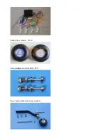


5.Use your radio system to center the rudder servo and attach either the supplied arm or an appropriate arm
for your servo. Thread one of the ball links about half way onto one of the threaded couplers. Feed the
loose end of one of the cables through a brass tube and then through the threaded coupler. Holding the
rudder centered, adjust the cable length as tight as possible while checking the ball link position over the
servo arm. When satisfied with the position, pinch the cable around the threaded coupler and then feed the
loose end back through the brass tube. Loop the cable back through the brass tube as before and crimp the
brass tube three times just tight enough not to cut the brass tube but enough to securely hold the wire in
place. Cut off the excess cable with wire cutters. Wick thin CA into the brass tube to help hold the cable
secure. Repeat for the other cable. Hint: Once you have established the position of the threaded coupler
on the cable, you can remove the ball link from the rudder horn to give you more working slack in the
fuselage. Re-install the ball link prior to setting the other cable.
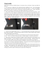
6. Check the operation of the rudder using your radio and make sure there is no
binding and the cables are
adjusted properly. You may have to tighten the cables after a few flights as they may stretch slightly from
the initial installation.
Summary of Contents for SLICK540 120E
Page 1: ...ARF MODEL 74in SLICK540 30CC 120E Instruction Manual ...
Page 9: ... Larger carbon fiber wing tube diameter than V1 Previous versions Scheme A Yellow white black ...
Page 10: ...Scheme B Red white black ...
Page 40: ......
Page 46: ... 3in Nylon Spinner with Aluminium Backplate No KAG0197 ...