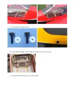


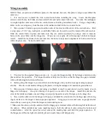


8. Cut the covering from the aileron servo openings from corner to corner and iron down inside the openings.
Connect servo wire extensions to your servos and secure the connections with the supplied clips, your own
clips, or tape. Feed the servo wires into the wing and out the root. Install the servos and screw firmly in
place.
9. Use your radio to set the centers of each servo and then assemble and adjust the length of each control rod.
The servo arm should be as close to perpendicular to the control rod as possible while the aileron is at
neutral. Double check all screws, bolts and nuts to assure proper installation and operation without
binding.Once satisfied, permanently attach the ball link to the servo arm with the supplied screw and nut.
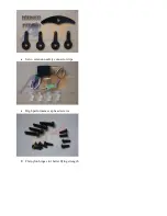
10. Check the final radio operation of the ailerons and make sure there is no binding or servo fighting of
each other. Also check to make sure all linkage bolts and nuts are secure.
11.
We recommend using KUZA 1.5” aluminium CNC servo arm (sold separately) for wing control.
Summary of Contents for SLICK540 120E
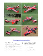
Page 1: ...ARF MODEL 74in SLICK540 30CC 120E Instruction Manual ...
Page 9: ... Larger carbon fiber wing tube diameter than V1 Previous versions Scheme A Yellow white black ...
Page 10: ...Scheme B Red white black ...
Page 40: ......
Page 46: ... 3in Nylon Spinner with Aluminium Backplate No KAG0197 ...