


6-17
6
AF894D
11. Install the wheels and tighten to specifications.
12. Remove the ATV from the support stand.
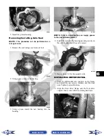
Drive Axles
REMOVING REAR DRIVE AXLE
1. Secure the ATV on a support stand to elevate the
wheels.
2. Compress the hand brake; then engage the brake
lever lock.
3. Remove the wheel.
4. Remove the cotter pin securing the hex nut; then
remove the hex nut. Release the brake lever lock.
KX041
5. Remove the two brake calipers (right side only).
NOTE: Do not allow the brake calipers to hang
from their cable/hose.
6. Slide the hub out of the knuckle and set aside.
7. Remove the cap screw and lock nut securing the
knuckle to the upper A-arm. Discard the lock nut.
NOTE: Never reuse a lock nut. Once a lock nut
has been removed, it must be replaced with a new
lock nut.
8. While holding the drive axle stationary, pull the
top of the knuckle out and down until it is free of
the drive axle.
9. Place a drain pan under the ATV to contain any oil
leakage; then using a slide hammer, remove the
drive axle.
AF935
REMOVING FRONT DRIVE AXLE
NOTE: For removing a front drive axle, see
Front Differential in this section.
CLEANING AND INSPECTING
NOTE: Always clean and inspect the drive axle
components to determine if any service or replace-
ment is necessary.
1. Using a clean towel, wipe away any oil or grease
from the axle components.
! WARNING
Make sure the ATV is solidly supported on the sup-
port stand to avoid injury.
! CAUTION
The calipers should be supported. If the calipers are
allowed to hang from the cable/hose, damage may
occur.
Back to TOC
Back to Section TOC
Next
Back


