


6-21
6
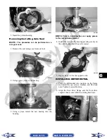
5. Compress the hand brake lever; then engage the
brake lever lock.
6. Tighten the hub hex nut (from step 3) to specifica-
tions; then install and spread a new cotter pin mak-
ing sure each side of the pin is flush to the hub nut.
CD027
7. Install the wheel. Tighten to specifications.
8. Remove the ATV from the support stand and
release the brake lever lock.
INSTALLING FRONT DRIVE AXLE
1. Position the drive axle in the gear case and steer-
ing knuckle; then insert the upper A-arm ball joint
into the steering knuckle. Secure with a cap screw
tightened to specifications.
2. Place the brake hose into position on the upper
A-arm; then secure the lower shock eyelet to the
A-arm with a cap screw and a new lock nut.
Tighten to specifications.
3. Secure the tie rod to the steering knuckle with a
new lock nut. Tighten securely; then install and
spread a new cotter pin.
4. Slide the hub w/brake disc into position in the
steering knuckle followed by a washer and hex
nut. Tighten finger-tight at this time.
5. Install the brake caliper on the steering knuckle.
Tighten to specifications; then pump up the hand
brake lever and engage the brake lever lock.
6. Tighten the hub hex nut (from step 4) to specifica-
tions; then install and spread a new cotter pin mak-
ing sure each side of the pin is flush to the hub nut.
CD027
7. Install the wheel and tighten to specifications.
8. Remove the ATV from the support stand and
release the brake lever lock.
9. Check the front differential lubricant level and add
lubricant as necessary.
CF113A
Rear Gear Case
REMOVING
1. Remove the left-side rear A-arms (see Rear
A-Arms in Section 7).
2. Remove both of the rear drive axles (see Drive
Axles in this section).
3. Remove the four cap screws securing the engine
output shaft to the rear gear case input flange.
Back to TOC
Back to Section TOC
Next
Back


