background image

Overview


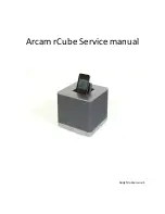
The


rCube


in


its


simplest


form


can


be


thought


of


as


a


high


performance


iPod


docking


station


with


more


than


a


few


unique


features


these


include.


Wireless


transmission


from


either


iPod


transmitter


(Arcam


Wand)


or


USB


(Arcam


Wave)


these


are


both


optional


extras.


rCubes


can


transmit


to


each


other


from


a


docked


iPod


or


external


source


wired


source.


Internal


battery


power


supply.


Easily


replaceable


iPod


header


(covered


latter


in


manual).


Access


Although


very


compact


the


rCube


is


designed


to


be


serviceable


with


access


gained


from


underneath


to


all


electronic


circuits


(remove


the


four


rubber


feet)


you


will


see


four


Philips


screws,


once


these


are


removed


the


base


plate


can


be


lifted


away


exposing


the


main


circuit


board.


The


main


speaker


array


is


not


considered


a


serviceable


part


but


will


be


available


as


a


complete


assembly.


Please


see


detailed


exploded


view.


Circuit


description


PSU


and


charge


The


19V


D.C


PSU


for


the


rCube


is


derived


from


either


an


external


regulated


PSU


or


if


not


present


from


the


internal


lithium


ion


battery


packs


the


following


is


a


description


of


the


PSU


selection.


The


external


19V


power


supply


is


connected


to


Con600


and


is


internally


fused


by


the


4A


fuse


at


location


FS600


the


rear


panel


switch


can


be


seen


at


location


SW600(a),


D600


is


used


to


prevent


reverse


bias,


D602


and


TR600


from


a


D.C


sense


circuit


this


line


goes


to


the


main


micro


at


location


U301


pin


7.


PSU


selection


is


control


by


the


MAX1873


Switch


mode


Li


charge


controller


at


location


IC603


the


external


19v


source


can


be


seen


to


arrive


at


pin


15


(DCin)


and


when


present


simply


by

passes


the


chip


whilst


being


monitored


by


pins


1/2


(current


sense)


and


can


be


seen


to


form


the


19v


source


net


on


the


diagram.


The


internal


battery


source


can


be


seen


connected


to


CON602


and


again


travels


thru


the


2

nd


pole


of


switches


available


on


SW600(b)


D605


and


TR603


are


used


to


form


simple


logic


to


indicate


to


micro


U301


that


battery


power


is


present,


D606


allows


a


path


to


the


main


19v


net


whilst


preventing


reverse


bias,


the


Mosfet


(M601)


is


used


to


enable


charge


if


necessary


when


power


is


present


the


entire


circuit


is


overseen


by


the


main


micro


U301


via


Summary of Contents for RCUBE

Page 1: ...Arcam rCube Service manual Andy Moore issue 1 ...

Page 2: ...gulated PSU or if not present from the internal lithium ion battery packs the following is a description of the PSU selection The external 19V power supply is connected to Con600 and is internally fused by the 4A fuse at location FS600 the rear panel switch can be seen at location SW600 a D600 is used to prevent reverse bias D602 and TR600 from a D C sense circuit this line goes to the main micro ...

Page 3: ...limited 5v supply to the iPod to whilst also preventing an over current situation at the rear panel USB input 3v1 this is reported to the main micro via the USB_PWR_FAULT line REG604 LDO provides a 3v1 supply to the Kleer and R F circuits and is sourced from the 5v supply IC600 is a charge pump convertor on the 5VA power supply rail Micro The Micro is shown in two halves on the diagram shown as IC...
Page 4: ...SPI_CS IC405 and debug 37 UC595_LATCH 8 bit shift register at location IC301 A 38 USB_PWR_FAULT From IC601 41 SPI_MODE0 Receive Transmit toggle via IC403 42 SPI_MODE1 Receive Transmit toggle via IC403 43 VID_CABLE_1 From multi pin video connector at location SKT200 44 IR_EYE From iPod header interface 45 CHARGE_DISABLE To IC603 via Mosfet M602 46 ATMEL_ OE 47 UART_UC_TO_KLEER Kleer interface data ...

Page 5: ...e Analog Devices DSP chip at location IC400 allowing for not only the High Low pass filtering of channels for the power amp stage but also bespoke audio manipulation the analogue audio from either docked iPod or Aux L R in appearing at pins 78 79 a Wolfson WM8805 running form a ref 11 2896Mhz clock is used primarily for Jitter reduction for the Kleer input chip at Location IC407 it is important to...

Page 6: ...citors based around C326 and C327 in combination with C510 audio then passes into the Volume control IC at location IC501 on pin 1 and can be seen to exit volume adjusted on pin 14 the volume control is under control of the main micro at position U302 via line VOL_CLK VOL_DAT the line will know be known as TWEET_VOL_R and travels into the Power amp chip at location IC507 shared with TWEET_VOL_L th...

Page 7: ...by input LED Mode Illumination Syncing to docked iPod Flashing green Sync complete Solid green Mode indicated by wireless LED Mode Illumination No available lock Red Lock present Green Searching for link hold wireless key 5 secs Flashing red Mode indicated by Vol LEDS Mode Illumination Mute Both LEDS on green The IR sensor at location RX1 is connected directly to U301 and runs from the 3V14 supply...

Page 8: ...ftware Download the latest SW version available from support arcam co uk or local distributor Load this onto a USB memory stick this needs to be a standard memory stick not on that carries a boot loader such a Cruzors With the cube in standby Press and hold the top plate standby button for 5 seconds Standby LED should start to flash with a frequency of 2 time a second Place memory stick in rear pa...

Page 9: ... Notes for mac users The USB update should be stick should be formatted to FAT32 standard and the only file present on the stick should be the software update i e no indexing files such as DS_Store files thumbs db files use a software such Cleanmymac available at http www macpaw com uk cleanmymac features You are interested in the Device Cleanup feature ...

Page 10: ... HOST_SPI_DATA_OUT HOST_SPI_CS HOST_SPI_CLK HOST_SPI_DATA_IN KLR3012_RF KLEER_SDATA_DIR KLEER_RESET SPDIF_RST I2C_SCL I2C_SDA UART_UC_TO_KLEER UART_KLEER_TO_UC DIV_CTRL RX_EN TX_EN DSP_RES DSP_I2C_SDA DSP_I2C_SCL WOOF_L WOOF_R TWEET_L TWEET_R IPOD_AUX_R IPOD_AUX_L U_L182_1 L182_1 0 SoundCube kleer DSP SchDoc I2C_SDA I2C_SCL I2C_SDA I2C_SCL Audio in Video out Host Micro PSU Battery charger Kleer mo...

Page 11: ...V0RETURN P0CON200016 P0P2050TP P0R20601 N0IPOD0AUDIO0L P0CON200018 P0P2030TP P0R20001 N0IPOD0AUDIO0R P0CON20002 N0IPOD0DETECT P0IPOD0DETECT P0CON20005 N0IPOD0TO0UC0RS232 P0IPOD0TO0UC0RS232 P0CON200011 N0IR0EYE P0IR0EYE P0CON20001 N0MICRO0READY P0MICRO0READY P0C20101 P0IC201A03 P0P2000TP P0R20002 P0R20102 P0C20201 P0P2020TP P0IPOD0AUX0R P0C20202 P0IC200A02 P0IC200C010 P0P2010TP P0R20401 P0C20401 P0...

Page 12: ...01B023 P0IC301B049 P0IC302B08 P0IC3030GND P0IC30402 P0R30202 P0R31802 P0R31902 P0R32002 P0R32202 P0CON30301 P0IC301A035 P0P3160TP P0R32001 N0HOST0SPI0CLK N0HOST0SPI0CLK N0HOST0SPI0CLK N0HOST0SPI0CLK P0HOST0SPI0CLK P0CON30303 P0IC301A036 P0P3150TP P0R31702 N0HOST0SPI0CS N0HOST0SPI0CS N0HOST0SPI0CS N0HOST0SPI0CS P0HOST0SPI0CS P0CON30304 P0IC301A060 P0P3170TP N0HOST0SPI0DATA0IN N0HOST0SPI0DATA0IN N0H...

Page 13: ...C408B015 N0HOST0SPI0DATA0OUT P0HOST0SPI0DATA0OUT P0IC40104 N0I2C0SCL P0I2C0SCL P0IC40107 N0I2C0SDA P0I2C0SDA P0R40101 N0IPOD0AUX0L P0IPOD0AUX0L P0R42401 N0IPOD0AUX0R P0IPOD0AUX0R P0IC404B04 P0P4390TP P0R42202 P0TR4000C N0KLEER0DATA0DIR0IN P0R42302 P0TR4010B N0KLEER0RESET P0KLEER0RESET P0IC404A01 P0TR4000B N0KLEER0SDATA0DIR P0KLEER0SDATA0DIR P0IC40703 N0KLR30120RF P0KLR30120RF P0IC400A036 P0P4080TP...

Page 14: ...TP P0R50702 P0C51502 P0IC503A01 P0P5310TP P0R50301 P0R51102 P0C52002 P0R52001 P0C52102 P0R52201 P0C52801 P0P5390TP P0R52002 P0R52101 P0R52601 P0C52901 P0IC500B06 P0P5400TP P0R52102 P0C52902 P0IC500B07 P0P5410TP P0R51801 P0R52602 P0C53001 P0P5370TP P0R52202 P0R52301 P0R52701 P0C53101 P0IC503B06 P0P5380TP P0R52302 P0C53102 P0IC503B07 P0P5420TP P0R51901 P0R52702 P0C53202 P0IC504025 P0P5500TP P0R52802...

Page 15: ...0R61202 P0R61602 P0R61902 P0R62002 P0R62402 P0R62702 P0R63502 P0REG60009 P0REG600012 P0REG6010GND P0REG60209 P0REG602012 P0REG60309 P0REG603012 P0REG603017 P0REG60406 P0REG60409 P0SP6000STARPAD1 P0SP6000STARPAD2 P0SP6000STARPAD3 P0SP6000STARPAD4 P0SP6000STARPAD9 P0SP6000STARPAD10 P0TR6000E P0TR6010E P0TR6020E P0TR6030E P0TR6040E P0C62802 P0C62902 P0C63502 P0C63602 P0C63702 P0C63801 P0C63901 P0C640...

Page 16: ...RL P0IC700B04 P0IC70304 P0P7050TP N0DIV0CTRL N0DIV0CTRL P0C70302 P0C70402 P0C70502 P0C70602 P0C71102 P0C71202 P0C71302 P0C71402 P0C71802 P0C71902 P0C72002 P0FL70002 P0FL70003 P0FL70005 P0FL70101 P0FL70103 P0FL70104 P0FL70106 P0IC700C02 P0IC70102 P0IC70202 P0IC70302 P0IC70407 P0IC70502 P0L70402 P0L70502 P0R70602 P0R70901 P0R71201 P0SKT7000GND1 P0SKT7000GND2 P0SKT7010GND1 P0SKT7010GND2 P0C70701 N0KL...

Page 17: ...R1001 P0R1002 P0R1101 P0R1102 P0R1201 P0R1202 P0R1301 P0R1302 P0R1401 P0R1402 P0R1501 P0R1502 P0R1601 P0R1602 P0RX10GND P0RX10OP P0RX10VCC P0SW101 P0SW201 P0SW301 P0SW401 P0SW501 P0TR10B P0TR10C P0TR10E P0TR20B P0TR20C P0TR20E P0TR30B P0TR30C P0TR30E P0TR40B P0TR40C P0TR40E P0TR50B P0TR50C P0TR50E P0TR60B P0TR60C P0TR60E P0TR70B P0TR70C P0TR70E P0TR80B P0TR80C P0TR80E P0C201 P0C901 P0C1001 P0C1901...

Page 18: ... 0 20 ANGULAR TOL 2 DEGREES 0 70 90 ALL DIMENSIONS IN MILLIMETERS UNLESS OTHERWISE STATED 20 E F 6 DATE DRAWN BY 1 3 F A3 A 4 CHECKED BY 4 MATERIAL B C DRAWING TITLE 10 A 30 ORIGINAL SCALE 1 2 FINISH 8 50 2 2 8 7 6 D SHT 1 OF 5 7 A R CAMBRIDGE LTD PART NUMBER AND DRAWING NUMBER D 23425 60 E 100 1 3 B C 40 DATE CHG ZONE DESCRIPTION OF CHANGE REL DR CHK ECO NR MCM 12 10 2010 MGB CUBE MAIN ASSEMBLY B...

Page 19: ... TOL 2 DEGREES 0 70 90 ALL DIMENSIONS IN MILLIMETERS UNLESS OTHERWISE STATED 20 E F 6 DATE DRAWN BY 1 3 F A3 A 4 CHECKED BY 4 MATERIAL B C DRAWING TITLE 10 A 30 ORIGINAL SCALE 1 2 5 FINISH 8 50 2 2 8 7 6 D SHT 2 OF 5 7 A R CAMBRIDGE LTD PART NUMBER AND DRAWING NUMBER D 23425 60 E 100 1 3 B C 40 DATE CHG ZONE DESCRIPTION OF CHANGE REL DR CHK ECO NR MCM 12 10 2010 MGB CUBE MAIN ASSEMBLY MAIN PCB TOP...

Page 20: ... 10 OTHERWISE STATED 0 0 0 20 ANGULAR TOL 2 DEGREES 0 70 90 ALL DIMENSIONS IN MILLIMETERS UNLESS OTHERWISE STATED 20 E F 6 DATE DRAWN BY 1 3 F A3 A 4 CHECKED BY 4 MATERIAL B C DRAWING TITLE 10 A 30 ORIGINAL SCALE 1 2 FINISH 8 50 2 2 8 7 6 D SHT 3 OF 5 7 A R CAMBRIDGE LTD PART NUMBER AND DRAWING NUMBER D 23425 60 E 100 1 3 B C 40 DATE CHG ZONE DESCRIPTION OF CHANGE REL DR CHK ECO NR MCM 12 10 2010 ...

Page 21: ...DEGREES 0 70 90 ALL DIMENSIONS IN MILLIMETERS UNLESS OTHERWISE STATED 20 E F 6 DATE DRAWN BY 1 3 F A3 A 4 CHECKED BY 4 MATERIAL B C DRAWING TITLE 10 A 30 ORIGINAL SCALE 1 1 FINISH 8 50 2 2 8 7 6 D SHT 4 OF 5 7 A R CAMBRIDGE LTD PART NUMBER AND DRAWING NUMBER D 23425 60 E 100 1 3 B C 40 DATE CHG ZONE DESCRIPTION OF CHANGE REL DR CHK ECO NR MCM 13 9 2010 MGB CUBE MAIN ASSEMBLY iPOD DOCK ...

Page 22: ...ES UNLESS 0 00 0 10 OTHERWISE STATED 0 0 0 20 ANGULAR TOL 2 DEGREES 0 70 90 ALL DIMENSIONS IN MILLIMETERS UNLESS OTHERWISE STATED 20 E F 6 DATE DRAWN BY 1 3 F A3 A 4 CHECKED BY 4 MATERIAL B C DRAWING TITLE 10 A 30 ORIGINAL SCALE 1 1 FINISH 8 50 2 2 8 7 6 D SHT 5 OF 5 7 A R CAMBRIDGE LTD PART NUMBER AND DRAWING NUMBER D 23425 60 E 100 1 3 B C 40 DATE CHG ZONE DESCRIPTION OF CHANGE REL DR CHK ECO NR...

Page 23: ...NS MUST BE TAKEN TO AVOID DAMAGE TO ELECTRONIC COMPONENTS 2 SLIDE DOCK REARWARDS AGAINST SPRING PRESSURE 1 PARTLY OPEN DOCK FLAP 1 REMOVE RUBBER FEET FROM BASE OF UNIT 2 REMOVE SCREWS BASE COVER TO REPLACE BATTERY 3 REMOVE BATTERY RELEASE CONNECTOR 4 FIT NEW BATTERY CONNECTOR REVERSE REMOVAL INSTRUCTIONS FIT NEW SELF ADHESIVE FEET SUPPLIED DANGER OF EXPLOSION IF BATTERY IS INCORRECTLY REPLACED REP...

Page 24: ...e ltd it s approved distributors and affiliated service agents No part of this manual may be transferred to any other party without express permission of A R Cambridge ltd This manual has been generated with great care it is intended for information only and no liability shall be accepted for errors or changes to specification A R Cambridge Ltd Pembroke Avenue Waterbeach Cambridge England CB25 9QR...

Reviews: