background image

- 50 -

BIOS

The AMI BIOS provides a setup utility program for specifying the system

configurations and settings which are stored in the BIOS ROM of the system. 

When you turn on the computer, the AMI BIOS is immediately activated. After 
you have entered the setup utility, use the left/right arrow keys to highlight a 

particular configuration screen from the top menu bar or use the down arrow 

key to access and configure the information below.

NOTE: In order to increase system stability and performance, our engineering 
staff are constantly improving the BIOS menu. The BIOS setup screens and 
descriptions illustrated in this manual are for your reference only, and may not 
completely match what you see on your screen.

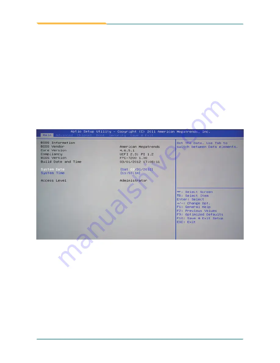
5.1  BIOS Main Setup

BIOS Information

Display the BIOS information.

System Date

Set the system date. Note that the ‘Day’ automatically changes when you set 
the date.
The date format is: 

Day : 

Sun to Sat

   Month 

1 to 12

   Date 

1 to 31

   Year 

1999 to 2099

Summary of Contents for FPC-7200 Series

Page 1: ...FPC 7200 Series Fanless Intel Atom D2700 Box PC User s Manual Version 1 0 2012 03 P N 4012720000100P...

Page 2: ...This page is intentionally left blank...

Page 3: ...ine of FPC 7200 13 2 1 Board Layout 14 2 2 Jumpers and Connectors 15 2 2 1 Jumpers Connectors List 15 2 2 2 Jumper Setting 16 JBAT1 Clear CMOS Setting 16 JP1 RS485 AUTOFLOW Selector 16 JP2 COM3 COM4 P...

Page 4: ...2 4 LAN 46 Chapter 5 BIOS 49 5 1 BIOS Main Setup 50 5 2 Advanced Settings 51 5 2 1 ACPI Settings 52 5 2 2 CPU Configuration 53 5 2 3 IDE Configuration 54 5 2 4 USB Configuration 55 5 2 5 F81866 Super...

Page 5: ...ontacting Technical Support This product has passed the CE test for environmental specifications when shielded cables are used for external wiring We recommend the use of shielded cables This kind of...

Page 6: ...s PBDE in electrical and electronic products Member states of the EU are to enforce by 7 1 2006 ARBOR Technology Corp hereby states that the listed products do not con tain unintentional additions of...

Page 7: ...THE OPENINGS 7 Position the power cord so that people cannot step on it Do not place anything over the power cord 8 Never pour any liquid into opening This may cause fire or electrical shock 9 Never...

Page 8: ...to a risk of explosion The lithium battery must be replaced with an identical battery or a battery type recommended by the manufacturer Do not throw lithium batteries into the trashcan It must be disp...

Page 9: ...se of or inability to use this product Vendor will not be liable for any claim made by any other related party Vendors disclaim all other warranties either expressed or implied including but not limit...

Page 10: ...vi This page is intentionally left blank...

Page 11: ...1 General Information 1 Chapter 1 General Information...

Page 12: ...nd cause dust to circulate inside the equipment The modular design facilitates maintenance or possible upgrades on the CPU board Modular Box PC can be easily modified to fit many different application...

Page 13: ...ng items 1 x FPC 7200 Box PC 1 x Accessory Box Driver CD User s Manual Screws Cable Terminal Block The following items are normally optional but some vendors may include them as a standard package or...

Page 14: ...wiring WiFi 3500 802 11 b g n WiFi module kit w 2dBi WiFi antenna 15cm internal wiring ML 3C 2G Single Side DDR3 2GB Long DIMM Kit Windows 7 32bit Driver Path CHIPSET Chipset Win7_x86 VGA VGA Win7_x86...

Page 15: ...Ports Serial Port 4 x DB 15 male connector Support 4 x RS 232 ports COM1 2 are RS 232 optional isolated COM3 4 are RS 232 485 selectable Expansion Bus 1 x Mini card slot 1 x SIM socket for optional W...

Page 16: ...random operation Shock Crash Operating 20G 11ms Non operating 40G with HDD Operating 40G 11ms Non operating 60G with CF SSD Crash 80G 11ms Mechanical Construction Aluminum alloy Mounting Support wall...

Page 17: ...7 General Information 1 6 Dimensions 224 00 207 00 6 00 Unit mm 4 00 92 00 92 00 219 00 268 00 195 00 80 00 86 00 NUT UNC 6 32...

Page 18: ...external peripheral devices such as a mouse a keyboard a monitor serial devices or printer etc Before connecting make sure that the computer and all peripheral devices are turned off 1 8 Connecting Pe...

Page 19: ...e cable being usable in either digital or analog situations 1 8 2 Serial Ports COM1 4 FPC 7200 is built with an integrated serial port that combines COM1 COM4 into a D sub 9 female connector Each port...

Page 20: ...off the BOX PC system and the Ethernet hub 2 Plug one cable end from a 10 100 1000Base T hub in the system s RJ 45 jack 1 8 3 LAN Ports 1 8 4 USB Ports FPC 7200 has ten USB ports on the front panel t...

Page 21: ...Keyboard and Mouse FPC 7200 has two PS 2 keyboard mouse connectors located at the front panel FPC 7200 has one PCIe slot located at the rear panel 1 8 6 Expansion PCIe Slot To connect an AT keyboard...

Page 22: ...d Power ON OFF Button For DC power input the computer is equipped with a 4 pin terminal block receptacle on the rear panel The S W button located on the front panel is used to power ON OFF the compute...

Page 23: ...13 The Engine of FPC 7200 2 Chapter 2 The Engine of FPC 7200...

Page 24: ...14 The Engine of FPC 7200 2 1 Board Layout The engine of FPC 7200 is FMB i2500 JBAT1 1 DIO1 FAN2 RSTB1 DP1 JP2 3 BZ1 FAN1 JP3 4 JP4 5 JP1 2 6 7 8 9 10 11...

Page 25: ...ting JP1 RS485 AUTOFLOW Selector JP2 COM3 COM4 PORT RS232 485 MODE Selector JP3 COM3 PORT RS232 485 MODE Selector JP4 COM4 PORT RS232 485 MODE Selector Label Function DIO1 Digital I O Box Header BZ1 B...

Page 26: ...de Default RS 485 Mode RS 232 Mode Default RS 485 Mode 1 2 Short Open 3 4 Open Short 5 6 Open Short 7 8 Open Short 9 10 Short Open 11 12 Open Short 13 14 Open Short 15 16 Open Short JBAT1 Clear CMOS S...

Page 27: ...2 Short Open 13 14 Short Open 15 16 Short Open JP3 COM3 PORT RS232 485 MODE Selector 4 Connector type Onboard 2x8 pin 1 27mm pin header JP4 COM4 PORT RS232 485 MODE Selector 5 Connector type Onboard 2...

Page 28: ...scription Pin Description 1 LEDG 2 DGH 3 LEDA 4 LEDB 5 NC 6 LEDC 7 LEDF 8 LEDE 9 DG L 10 LEDD DIO1 Digital I O Box Header 6 Connector type Onboard 2 54mm pitch 16 pin BOX header DP1 External 80 Port P...

Page 29: ...on 2 1 1 GND 2 SYS_RESET Pin Description 1 3 1 GND 2 12V 3 Fan CTL RSTB1 Reset Button Pin Header 9 Connector type Onboard 2 54mm pitch 2 pin header for debug use only FAN1 2 FAN Connectors 10 11 Conne...

Page 30: ...20 This page is intentionally left blank...

Page 31: ...21 Installation and Maintenance 3 Chapter 3 Installation and Maintenance...

Page 32: ...ecure the top cover 2 Use a screwdriver to remove the top cover screws First unscrew the four screws in each corner and then the two screws in the middle of the two sides Retain the screws safely for...

Page 33: ...Memory DIMM slot 2 Gently push the Memory module in an upright position and a right way until the clips of the DIMM slot close to lock the Memory module in place when the Memory module touches the bo...

Page 34: ...cate Mini card socket insert the HSUPA module into it at a slanted angle as shown in the picture Be sure to align the notch on module with the break on socket And then secure two screws to fasten the...

Page 35: ...lug outwards to remove it so that another end of RF cable which is a SMA connector jack can penetrate through antenna hole located on front panel of the chassis Retain the plastic plug for later use W...

Page 36: ...n and Maintenance 4 Mount a round washer into the SMA connector jack from outside before securing another nut into it 5 At the end screw antenna into the SMA connector jack and adjust antenna angle fo...

Page 37: ...ast card 2 Locate the CFast SIM card door on the front panel 3 Use a crosshead screwdriver to loose the screw that secures the CFast SIM card door Open the door by dragging it out firstly Remember to...

Page 38: ...28 Installation and Maintenance 5 To remove the CFast SIM card push that inwards to pop it out...

Page 39: ...Installing Hard Disk Drive 1 Locate the four screws securing the HDD Holder Bracket to the main unit 2 Unscrew the screws and remove the HDD Holder Bracket Keep the screws safely for later use 2 Use...

Page 40: ...30 Installation and Maintenance 3 Carefully put the 2 5 HDD into the HDD Holder Bracket and screw its four corners Be sure to align its connector with HDD socket 4 Secure bracket on main unit 2 5 HDD...

Page 41: ...tion and Maintenance 3 3 2 Installing Riser Card 1 Unscrew riser card bracket with screwdriver Take the bracket off and keep it for later use 2 Plug your desired PCIe x1 card into appropriate place an...

Page 42: ...ver 3 Secure the brackets to the main unit with the accompanying screws 3 5 Grounding the Box PC Follow the instructions below to ground the box PC onto land Be sure of following any grounding require...

Page 43: ...DC power source 4 Identify the positive and negative feed positions for the terminal block connection See the symbols printed on the rear panel indicating the polarities and DC input power range in v...

Page 44: ...34 This page is intentionally left blank...

Page 45: ...35 Driver AP 4 Chapter 4 Driver AP...

Page 46: ...appropriate instal lation procedure is as below CHIPSET VGA AUDIO LAN Please Follow This Procedure to install all necessary units in most cas es or you may encounter errors Also the correct driver AP...

Page 47: ...1 Execute infinst_autol exe in the suggested path CHIPSET INF 9 2 0 1030 Always click Yes whenever Windows 7 inquires you Do you want to allow the following programs to make changes to this computer 4...

Page 48: ...38 Driver AP 4 Click Yes 3 Wait for extracting...

Page 49: ...39 Driver AP 6 Click Finish 5 Click Next...

Page 50: ...40 Driver AP 1 Execute Setup exe in the suggested path GRAPHICS INTEL_ WIN7_32 2230 4 2 2 VGA 2 Click Next...

Page 51: ...41 Driver AP 3 Click Yes 4 Click Next...

Page 52: ...42 Driver AP 5 Wait for the process 6 Click Next...

Page 53: ...43 Driver AP 7 Click Yes to restart computer 4 2 3 Audio 1 Execute Vista_Win7_R261 32_64 exe in the suggested path AUDIO REALTEK_HD Vista_Win7_R261 32_64 bit...

Page 54: ...44 Driver AP 2 Wait for extracting 3 Keep waiting...

Page 55: ...45 Driver AP 4 Click Next 5 Wait for the process...

Page 56: ...46 Driver AP 6 Click Yes to restart computer 1 Execute setup exe in the suggested path ETHERNET REALTEK 8111B_Win7_7046 4 2 4 LAN...

Page 57: ...47 Driver AP 2 Click Next 3 Click Install...

Page 58: ...48 Driver AP 4 Wait for the process 5 Click Finish...

Page 59: ...49 BIOS 5 Chapter 5 BIOS...

Page 60: ...e down arrow key to access and configure the information below NOTE In order to increase system stability and performance our engineering staff are constantly improving the BIOS menu The BIOS setup sc...

Page 61: ...guration This section is used to configure the CPU It will also display detected CPU information ACPI Settings Set system ACPI parameters USB Configuration IDE Configuration Configure the USB devices...

Page 62: ...Disabled Default Enabled Enable Hibernation Enable or disable the Hibernation function This allows the operating system to control power to the computer s disk monitor and peripheral devices Setting...

Page 63: ...S optimized for Hyper threading Technology and disabled for other OS OS not optimized for Hyper threading Technology When disabled only one thread per enabled core is enabled Execute Disable Bit XD ca...

Page 64: ...troller SATA Port 0 1 SATA Controller s Port0 Speed Limit Enable or Disable SATA Port SATA Ports 0 3 Device Names if Present and Enabled Select Port0 AHCI Speed Limit Configure SATA as SATA Port 0 1 H...

Page 65: ...Hand Off Allows you to enable support for operating systems without an EHCI hand off feature Do not disable the BIOS EHCI Hand Off option if you are running a Windows operating system with USB device...

Page 66: ...Configuration Serial Port Set Parameters of Serial Port 0 1 2 3 COMA Enable or Disable Serial Port COM Power On After Power Fail Change Settings Specify what state to go to when power is re applied af...

Page 67: ...57 BIOS 5 2 6 F81866 H W Monitor PC Health Status The hardware monitor menu shows the operating temperature fan speeds and system voltages...

Page 68: ...installed on your system The chipset manage bus speeds and access to system memory resources such as DRAM It also coordinates communications with the PCI bus Notice Beware of that setting inappropriat...

Page 69: ...OS 5 3 1 Host Bridge Auto Disable IGD Auto disable IGD upon external GFX detected IGFX Boot Type Select the Video Device which will be activated during POST This has no ef fect if external graphics pr...

Page 70: ...60 BIOS 5 3 2 South Bridge Enable or Disable the High Precision Event Timer High Precision Timer SLP_S4 Assertion Width Select a minimum assertion width of the SLP_S4 signal...

Page 71: ...ime you boot and can be turned off to save time When set to Enabled this option shortens POST by eliminating some tests Quiet Boot Bootup Numlock State This allows you to select the screen display whe...

Page 72: ...nter a password To disable a password just press Enter when you are prompted to enter the password A message will confirm the password will be disabled Once the password is disabled the system will bo...

Page 73: ...nd Exit Pressing Enter on this item and it asks for confirmation Save configuration changes and exit setup Pressing OK stores the selection made in the menus in CMOS a special section of memory that s...

Page 74: ...them corresponding to one device within the boot order Select a drive to immediately boot that device regardless of the current boot order Restore system to settings previously stored by Save as User...

Page 75: ...65 Appendix Appendix...

Page 76: ...grammable interrupt controller 0000002E 0000002F Motherboard resources 00000030 00000031 Programmable interrupt controller 00000034 00000035 Programmable interrupt controller 00000038 00000039 Program...

Page 77: ...00000A8 000000A9 Programmable interrupt controller 000000AC 000000AD Programmable interrupt controller 000000B0 000000B1 Programmable interrupt controller 000000B2 000000B3 Motherboard resources 00000...

Page 78: ...herboard resources 0000D000 0000D0FF Realtek PCIe GBE Family Controller 2 0000D000 0000DFFF Intel R N10 ICH7 Family PCI Express Root Port 27D2 0000E000 0000E0FF Realtek PCIe GBE Family Controller 0000...

Page 79: ...ller 0000F0E0 0000F0E3 Standard AHCI 1 0 Serial ATA Controller 0000F0F0 0000F0F7 Standard AHCI 1 0 Serial ATA Controller 0000F100 0000F107 Intel R Graphics Media Accelerator 3600 Series 0000FFFF 0000F...

Page 80: ...IRQ 101 Microsoft ACPI Compliant System IRQ 102 Microsoft ACPI Compliant System IRQ 103 Microsoft ACPI Compliant System IRQ 104 Microsoft ACPI Compliant System IRQ 105 Microsoft ACPI Compliant System...

Page 81: ...130 Microsoft ACPI Compliant System IRQ 131 Microsoft ACPI Compliant System IRQ 132 Microsoft ACPI Compliant System IRQ 133 Microsoft ACPI Compliant System IRQ 134 Microsoft ACPI Compliant System IRQ...

Page 82: ...Host Controller 27CB IRQ 16 Intel R N10 ICH7 Family PCI Express Root Port 27D0 IRQ 160 Microsoft ACPI Compliant System IRQ 161 Microsoft ACPI Compliant System IRQ 162 Microsoft ACPI Compliant System...

Page 83: ...t ACPI Compliant System IRQ 187 Microsoft ACPI Compliant System IRQ 188 Microsoft ACPI Compliant System IRQ 189 Microsoft ACPI Compliant System IRQ 19 Intel R N10 ICH7 Family USB Universal Host Contro...

Page 84: ...rosoft ACPI Compliant System IRQ 90 Microsoft ACPI Compliant System IRQ 91 Microsoft ACPI Compliant System IRQ 92 Microsoft ACPI Compliant System IRQ 93 Microsoft ACPI Compliant System IRQ 94 Microsof...

Page 85: ...el R N10 ICH7 Family PCI Express Root Port 27D2 DFD04000 DFD04FFF Realtek PCIe GBE Family Controller 2 DFE00000 DFE03FFF Realtek PCIe GBE Family Controller DFE00000 DFEFFFFF Intel R N10 ICH7 Family PC...

Page 86: ...oard resources FED45000 FED8FFFF Motherboard resources FEE00000 FEE00FFF Motherboard resources FF000000 FFFFFFFF Intel R 82802 Firmware Hub Device FF000000 FFFFFFFF Intel R 82802 Firmware Hub Device F...

Page 87: ...id main void int SMB_PORT_AD 0xF000 int SMB_DEVICE_ADD 0x6E 75111R s Add 6eh programming DIO as output 0 input 1 Output Index 10 GPIO1x Output pin control SMB_Byte_WRITE SMB_PORT_AD SMB_DEVICE_ADD 0x1...

Page 88: ...ar delay 10 outportb SMPORT 04 DeviceID 1 clear outportb SMPORT 03 REG_INDEX clear outportb SMPORT 02 0x48 read_byte delay 10 SMB_R inportb SMPORT 05 return SMB_R void SMB_Byte_WRITE int SMPORT int De...

Page 89: ...ing Below please take the source code written in C for a WDT application example Include Header Area include math h include stdio h include dos h index port 0x2e void main outportb 0x2e 0x87 initial I...

Reviews: