background image

 16


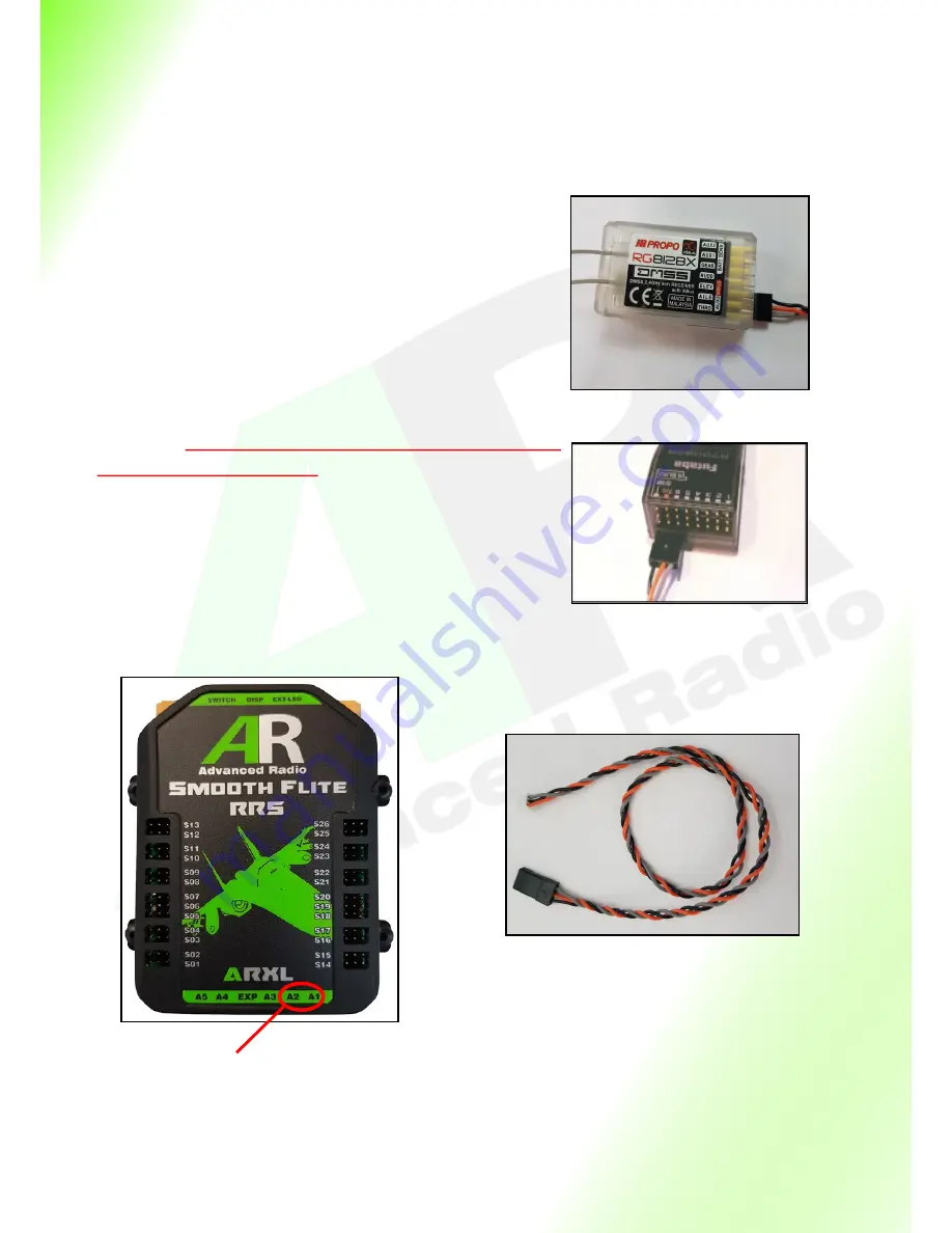
The SmoothFlite ARXL includes two receiver connection cables, these are designed to be plugged 
into the A1 and A2 at the base of the SmoothFlite. This cable can then be connected to the  
SBUS2, SRXL, JR XBus, Jeti EX Bus, HOTT port on your receiver. 


PLEASE NOTE the polarity of the receiver signal and ground on 
the receiver before connecting to the SmoothFlite.


The SmoothFlite system will work with either a single or dual 


receiver setup. The receivers 

MUST BE 

capable of 7.4V . 


We recommend using two HV (high voltage)  receivers or similar. 
If you are unsure please contact Advanced Radio for details.


The SmoothFlite System is designed to supply the power to all 
the  servos. NEVER connect servos directly to the receiver when 
using the SmoothFlite System.


It is very important that the polarity is connected correctly be-
tween the SmoothFlite and the receiver, if the polarity is con-
nected incorrectly this may damage the receiver and Smooth-
Flite. 


Note: For more information on how to setup and bind single or 
dual receivers, please consult your transmitter and receiver 
manual supplied by the manufacturer.


Spektrum Receivers = Connect to SRXL port .


Futaba Receivers = Connect to SBUS2 port.


JR/FDA Receivers = Connect to XBUS port.


JETI Receivers = Connect to EX BUS port.


Graupner Receivers = Connect to SUMD port. 


Ensure that the RRS cables sup-
plied is plugged into the R2 and 

R1 port of the Smart Bus


Redundant Receiver Cable


Installing the Receivers ARXL Version


Please note cable position on a  7008 receiver. 
It is possible to plug into the ground pins of the 
receiver and this may damage the receiver and 
SmoothFlite system.


Please note cable polarity on a RG812BX


Summary of Contents for SmoothFlite RRS

Page 1: ...SmoothFlite RRS User Guide ...

Page 2: ...5 Installing the Receivers ARXL Version 16 System Specific Receiver installation 17 Installing Satellites Spektrum Version 18 Input Channel to Servo Output Routing 19 20 Servo Sub trim Reversing Method 1 21 Servo Sub trim Reversing Method 2 22 15 Point Matching 23 Receiver Menu 24 Setting Fail Safe 25 Telemetry with Spektrum TM1000 26 Telemetry with SBUS2 Receivers 27 Factory Reset 28 Additional S...

Page 3: ...nel Assign Sequencer Config Manual Opera tion Power Up Logic Seq Factory Reset 51 Getting Started With Sequencer Set up 52 Set Master Switch 52 Global Servo Speed 52 Channel Assign 53 Sequencer Output Parameters Adjust OPEN Position Adjust CLOSED Position 54 Sequencer Manual Operation 55 Sequencer Power Up Logic Gear Position Master Switch Operation 56 Sequencer Factory Reset 56 Sequencer Config S...

Page 4: ...eter into the hardware The combination of these sensors gives you much more flexibility in flight stabilisation and that is why we called it SmoothFlite LETS GET STARTED in this guide we will show you how to connect your new SmoothFlite system General use and setup as well as how to get the most out of the SmoothFlite stabilisation system Please take the time to read understand this guide before i...

Page 5: ...ity 26 buffered fully assignable and programmable servo outputs Easy to use pre routed servo routing Independent servo reverse on all channels Sub Trim and end point 3 point matching on all channels Advanced 15 point matching on all channels Digitally selectable regulator output via the Smart Screen Regulator selectable to 6 0 volts 7 4volts Maximum Battery Power Balancing Using dual battery perfe...

Page 6: ...odel provides a low vibration environment Turbine Sail Plane Electric model then hard mounting of the Smart Screen is possible The Smooth Flite provides downlink telemetry so it is not necessary to mount the Smart Screen in the model to view battery data Mounting the SmoothFlite System The SmoothFlite is supplied with 4 rubber shock mounts in the base plate similar to rubber mounts on servos these...

Page 7: ... where you wish to mount it Holding it in place make a dot using a pen or pencil in each eyelet hole Removing the screen drill a hole where you placed the dots Now simply screw the Smart Display in place NOTE Hard mounting the Smart Display provides little to no protection against vibration Use this method if you are using a non vibration model or only where there is little to no vibration AVOID M...

Page 8: ... voltage of both battery packs Servo Shows Regulated voltage to servos Total mA Shows total milliamps since last charge Press here to enter the Main Menu Last mA Shows milliamps used since model was last powered up and resets when model is turned off Press here to reset flight timer and Last mA FL T Flight timer since model was turned on The timer only operates while on the main screen FL N Flight...

Page 9: ...you to the SmoothFlite page available on SmoothFlite versions of SmoothFlite RRS Power Setup Screen Return Takes you back to the previous screen RES mA Resets total mA used Please ensure both packs are FULLY charged before you reset RES FLT Resets flight counter and timer to zero Use this feature mostly when installing in a new airframe or before the maiden flight Bat Capacity mA Shows the capacit...

Page 10: ...aves your routing choices and buttons Changes the input Channel from 1 to 20 Note you can only assign servos to channels that are available from your Receiver Example you can not assign a servo to channel 18 when using a 10 channel radio S01 to S26 These buttons correspond to the outputs on the SmoothFlite RRS They have 3 colours Green they are assigned to the current re ceiver channel Blue they a...

Page 11: ...creen and show corresponding assigned input to output channel s We will expand on this feature in the servo matching section Sub Trim Return Returns you back to the previous screen Sub Trim Level shifts the entire range of the chosen servo channel End Points End point adjustment to increase or reduce servo range Also used in conjunction to match multiple servos Sub Trim and End Point Menu Return R...

Page 12: ...h an incorrect checksum value Frame Rate Set the output frame rate of the signal to the servos Fail Safe Button Spektrum and JR version only Takes the user to the fail safe screen SBUS2 HOTT and Jeti EX failsafe is set in the transmitter Fail Safe Screen Spektrum and JR version only SBUS2 HOTT and Jeti EX failsafe is set in the transmitter Return Takes you back to the previous screen Vertical Bars...

Page 13: ...al We recommend you do not have any servos connected to the SmoothFlite during the first time setup Step 1 Ensure that both batteries are plugged into the SmoothFlite You will also need to en sure the Smart display is plugged into the switch as it is used for programming Upon power up you will see the AR logo After a few seconds the Smart Screen will be shown Step 2 Press the green Total mA text o...

Page 14: ...er is correct and accurate If you are unsure about the capacity of your batteries or if your packs are not new we recommend cycling your packs by discharging them and recharging them to full This will give you the best possible result for the battery packs you are using Step 5 Using the 6 0v and 7 4v buttons select the regulator voltage of your choice This will change the output voltage to your se...

Page 15: ... DFA X BUS JETI JETI EX Graupner HOTT Spektrum AR700 receiver SPEK SRXL Spektrum offer 2 different receiver protocols Spektrum SRXL is NOT compatible with Spektrum Satellite receivers and runs at a higher voltage DO NOT CONNECT Spektrum Satellite receivers to the multiprotocol ARXL version of the SmoothFlite The Spektrum Satellite version of SmoothFlite is a dedicated SmoothFlite system with diffe...

Page 16: ...g the SmoothFlite System It is very important that the polarity is connected correctly be tween the SmoothFlite and the receiver if the polarity is con nected incorrectly this may damage the receiver and Smooth Flite Note For more information on how to setup and bind single or dual receivers please consult your transmitter and receiver manual supplied by the manufacturer Spektrum Receivers Connect...

Page 17: ...f either receiver Telemetry of battery voltage current and mAh consumption are provided alternatively on the JR DFA transmitter Graupner HOTT System The current version of SmoothFlite operating system supports all receivers with HOTT protocol HOTT receivers provide up to 16 channels depending on receiver and transmitter into the SmoothFlite which can be routed to any of the 26 servo output channel...

Page 18: ...Telemetry is provided from the Smooth Flite EXP port to the TM1000 or receiver XBUS port You will require the an AR telemetry specific cable Do not use any other cable to connect the TM1000 to the Smooth Flite as this could damage the XBUS ports on the receiver and Smooth Flite Please contact AR for details Multiplex SRXL System The current version of SmoothFlite supports Multiplex SRXL protocol M...

Page 19: ... to its fullest potential During the setup if you have multiple servos on a control surface Example 2 servos on an aileron We recommend setting up the master servo before mechanically connecting the slave Step 1 Ensure that both batteries are plugged into the SmoothFlite You will need to plug in the Smart Screen as it is used for programming Ensure your receiver is plugged into the SmoothFlite and...

Page 20: ...tton on the Smart Screen The S13 should turn green We have now added servo output 13 S13 to transmitter input channel 1 SmoothFlite makes it that simple Tapping S13 a second time will de assign it turning it back to blue Note The servo channels are colour coded Green they are assigned to the current transmitter input channel Blue they are not assigned to any transmitter input channel and are avail...

Page 21: ...he SERVO ADJUST button This will take you directly to the servo match and sub trim screen pictures to the right Lets have a look at how to sub trim and reverse channel S01 on the SmoothFlite Simply tap on the servo output S01 You should now see the Sub Trim menu for S01 The words Editing S01 will be shown at the top right of the screen picture to the right This can be used to check you have select...

Page 22: ...ct channel Lets now reverse the servo Tap the SERVO DIRECTION button This will change the direction of rotation on the ser vo Tapping the SERVO DIRECTION button a second time will set it to its original direction Now lets have a look at sub trimming a servo Tap the Sub Trim Servo Match button to take you into the Sub Trim Page Press the Sub Trim buttons to sub Trim the servo This is the same as su...

Page 23: ...r rotary con trol for that channel from one side to the other if at any point you hear servo buzz Hold the transmitter stick in that position and use the buttons to sub trim at that point Sub trim the servo until the servo buzz lessens or disappears Step 4 Repeat Step 3 for the entire range of the servo this can be repeated as many times as you wish Step 5 Once you are happy with the sub trim pres...

Page 24: ...se consult your receiver manufacturer for more details on receiver placement The third column shows FAILSAFE Fail Safe events PER RECEIVER this value shows the number of failed to send events from a receiver to the SmoothFlite i e the SmoothFlite was expecting to receive frames but the receiver stopped sending them If you experience high numbers in FAILSAFE events during ground testing or after la...

Page 25: ... channels outputted from your radio Note The bars have two colours Blue FAILSAFE is set to heading hold In a FAIL SAFE event the channel and associated servos will hold the last good received channel value Green FAILSAFE is set to a specific position The channel and associated servos will move to the pre set FAILSAFE channel value The default setting for all channels is heading hold Blue bars Step...

Page 26: ...26 Page Intentionally Left Blank ...

Page 27: ...your transmitter Step 3 Ensure your transmitter is turned on Note For the following steps we will be using the 18SZ as an example For all other radios please consult your transmitter manual Select the linkage menu on your transmitter Now select the sensor menu Step 4 Page across until you see sensor slot 24 Assign Curr F1678 to this slot Step 5 Page across to slot 27 Assign Curr F1678 to this slot...

Page 28: ...erforming a Factory Reset will erase all sub trim data and is an irreversible pro cess Only do this if you are sure you want to reset the SmoothFlite to factory settings Step 1 Using the Smart Display go into the System menu once here press the FACTORY RESET button Step 2 A WARNING and Instructions will appear on screen Please Read this as it is an important process When ready press YES to continu...

Page 29: ...an cycle through the cockpit screens by tapping the area at the bottom of the Smart Screen If you want to make any of the cockpit screens for realistic effects or the battery monitoring screen the default screen simply power down the SmoothFlite while on the desired screen The SmoothFlite remembers the last cockpit or battery screen and will display this after the boot routine on power up To retur...

Page 30: ... This will take you to the SmoothFlite main Menu shown below Lets take a look at the various SmoothFlite menu options Return button Returns you to the main menu Wizard button This button will start the setup Wizard and guide you through the setup process Chan Assign button The Channel Assignment button will take you the setup page for channel assignment to Aileron 1 Ai leron 2 Elevator and Rudder ...

Page 31: ...f the SmoothFlite system to match your transmitter and receiver 2 Have not altered the factory input channel routing from the transmitter SmoothFlite uses factory input channel routing to simplify the setup process 3 Have a good understanding of the SmoothFlite Input channel to Output channel routing 4 Have assigned outputs to Ailerons Elevator and Rudder 5 Have a transmitter setup for the model a...

Page 32: ...Flite system and not in the transmitter Of course during the maiden flight you may need to trim on the transmitter but initial servo trim setup should be done in the SmoothFlite system We will explain why trimming in the SmoothFlite system is best as we go through the setup process OK lets get started From the SmoothFlite menu tap the Wizard button This will start the setup Wizard You will be pres...

Page 33: ... On Off and to select low and high speed gain settings You need to assign a 3 stage switch on the transmitter for this function along with a transmitter output channel Take the time to read this page and press NEXT Master Channel When you are ready toggle the Master Switch on the transmitter The Master Switch search function will find the assigned channel from the transmitter Once the channel has ...

Page 34: ...trol We suggest for the first flight you apply SmoothFlite to Rudder only so you can get a feel for flying with SmoothFlite You can always apply to Elevator and Ailerons at a later stage After making your selection SmoothFlite will store your choice then tap NEXT SmoothFlite Mounting The last thing we need to tell SmoothFlite is whether it is mounted UPRIGHT or INVERTED After you make your selecti...

Page 35: ... the rudder move to deflect further to the right then you can go to the Rudder page shown left and invert SF Out put This will change the rudder reaction to the op posite direction Elevator Check If you have activated Elevator to be controlled by SmoothFlite then moving the models tail up you should see the Elevator deflect upwards to counteract the movement If you see the Eleva tor move downwards...

Page 36: ...ke they have a lot of exponential ap plied This is quite normal The feeling will generally increase with higher gain and decrease with lower gain SmoothFlite is much more than just a gyro It offers several advanced proprietary features of Automatic Gain Control AGC Variable Gain Control VGC Aerobatic Mode and Proportional Modes to as sist with tuning your model and SmoothFlite experience We will n...

Page 37: ...he outer most points This gives more agility to the model as the stick is moved away from centre So at centre position SmoothFlite is 100 assisting with smoothing out the flight char acteristic where as at extreme outer positions SmoothFlite is assisting at approximately 50 Proportional modes can be applied individually to each control surface Variable Gain Control VGC In addition to setting high ...

Page 38: ... model If you ran the Wizard then this function would be active as shown in the picture Inverted Mount Tells SmoothFlite to calculate gyro positions based on the SmoothFlite Bus being mounted upright or inverted If you ran the Wizard and selected inverted then this function would be active as shown in the picture Master TX Switch This is the channel chosen on the transmitter to turn the gyro ON OF...

Page 39: ...gly recommend these are not altered away from factory setting on the transmitter unless you have a thorough understanding of input channel assignment Variable Gain Control VGC In addition to setting high speed and low speed gain settings on the Master Switch SmoothFlite offers an optional additional Variable Gain channel which can be assigned to say a rotary dial a switch or an advanced mix on the...

Page 40: ...u need to Invert SF Output as shown in the picture to the right De checking has the opposite effect IT IS VERY IMPORTANT that this parameter be set correctly SmoothFlite Automatic Gain Control AGC One of the symptoms of flying with too higher gain on the gyro is that the model may start to oscillate at higher gain settings At Advanced Radio we employed information gathered from several of the Smoo...

Page 41: ...off may result in control oscillations Note If you use the Auto Gain Control AGC feature then increasing these gain values may have little effect as the auto gain feature will control the maximum level of gain applied by SmoothFlite Invert Aileron 2 Clicking Invert Aileron 2 will invert the output of the SmoothFlite Effect to Aileron 2 Differential ON OFF INVERT Differential is used to achieve axi...

Page 42: ... developed our proprietary Automatic Gain Control AGC algorithm to cor rect this situation If activated the SmoothFlite Automatic Gain Control is constantly monitoring the flying characteristic of the model and applying gain up to the level you have chosen to suit the flying characteristic of the model No other speed sensing module is required SmoothFlite AGC can be individually applied to Aileron...

Page 43: ...ve been undertaken by our factory pilots to come up with default values have been to give good results Increasing gain levels to high with Auto gain Control switched off may result in control oscillations Note If you use the Auto Gain Control AGC feature then increasing these gain values may have little effect as the auto gain feature will control the maximum level of gain applied by SmoothFlite T...

Page 44: ...dder button from the SmoothFlite menu will take you to the Rudder Channel page SmoothFlite Rudder Automatic Gain Control AGC One of the symptoms of flying with too higher gain on the gyro is that the model may start to oscillate at higher gain settings At Advanced Radio we employed information gathered from several of the SmoothFlite sensors and have developed our proprietary Automatic Gain Contro...

Page 45: ...tle effect as the auto gain feature will control the maximum level of gain applied by SmoothFlite Testing has found ideal results are achieved with factory gain settings and AGC set to ON SmoothFlite Trim SmoothFlite uses maximum minimum and centre stick positions in many of its calculations If you have completed the wizard then you would have already captured these values However you can redo the...

Page 46: ...Check the AR product page for setup videos Elevons Elevator to Aileron mixing Selecting Elevons will cause several things to happen with the SmoothFlite setup The Tail Type page will display the mixing slider as well as the Invert Mix Direction checkbox button The Slider is used to apply More Less elevator to the aileron channels The Invert Mix Direction will cause the elevator mix applied to the ...

Page 47: ...er output to get a centred rudder Main Menu Monitor Tap the input channel indicator assigned to rudder Tap the Assigned To Smart Bus Output for rudder You will be in the Sub Trim page for the assigned Rudder where you can perform Sub Trim Reverse the servo if necessary and sub trim the steering output to get centred steering Also adjust end points in or out as required This can and should performe...

Page 48: ...your TX type Main Menu System Protocol type Route the TX elevator channel to 2 SmoothFlite servo outputs These will be eventually used for Canard control Main Menu I O Routing Route the TX left aileron channel to 2 SmoothFlite servo outputs and the TX right aileron channel to 2 servo outputs These will be used of Elevon and thrust vectoring Main Menu I O Routing Route the TX Rudder channel to 4 Sm...

Page 49: ...flap You will be in the Sub Trim page for the assigned Rudder where you can perform Sub Trim Reverse and Endpoint matching Hint Do the above process starting with the TX Flap switch or Dial is in the half position so as to not overdrive the servo Reverse if necessary sub trim and adjust endpoints so the primary flap operates to your requirements Once you are happy with the primary flap operation t...

Page 50: ...o and repeat the process Connect the Rudder Thrust vectoring servos and sub trim as necessary The Thrust vectoring should now follow the elevon and rudder movements Finally connect the CANARD servos and as above Sub Trim Reverse as necessary Hint With Canards and thrust vectoring you can drastically reduce or increase the end points in the SmoothFlite Sub Trim pages This functionality is available...

Page 51: ...uencers are allotted and used however to make the user experi ence easier we have created dedicated sequencing functions for easy operation This will become clearer as you start to use the sequencers To access any of the sequencers press the appropri ate sequencer button You will be shown the Sequencer Assign page for the chosen sequencer SQ Master Channel Shows the master channel value chosen to ...

Page 52: ...ge The letters NA will be replaced with the chosen Master Input channel If you have captured the wrong channel simply repeat the procedure above You can repeat this process as many times as needed Global Servo Speed When setting up a scale model sometimes we need to reduce the speed of linear actuators or servos to achieve a real scale effect The SmoothFlite sequencer offers an optional speed feat...

Page 53: ...s etc Assigning An Output Channel Lets assign an output channel to the gear function Tap the left most grey button marked NA on the top GEAR row This will take you to the SQ Chan 1 Param page where you can select any of the Smooth Flite s available physical output channels Smooth Flite will only allow you to select output chan nels that have not bee previously assigned in the Smooth Flite Output C...

Page 54: ...n position and then fine adjust the position Holding a button down will start adjusting in small increments and then step to large increments Adjust Closed Position Press and hold or to move the gear to the Closed or UP position and then fine adjust the position Hint Holding a button down will begin adjusting in small increments and then step up to large increments It is IMPORTANT that you set the...

Page 55: ...press this button then you WILL need to reverse the operation in the Smooth Flite Sequencer output channel from the parameters page Pressing Gear UP will cause the Gear UP button to change from BLACK to RED and SmoothFlite Channel 26 to move to the Gear UP position If you find that the gear lowers when you press this button then you WILL need to reverse the operation in the Smooth Flite Sequencer ...

Page 56: ...osition Factory default This is the setting where the gear and doors will move to the last position when power was removed Sequencer Switch position 1 Sequencer Arms From Gear Switch Down position Factory Default This means the gear switch must be moved to the down position before the sequencer will arm 2 Sequencer Arms In Any Position If the Master switch is in the gear down position then the seq...

Page 57: ...equencer stepping operation for a gear up sequence and gear down sequence For this example we will use a simple setup of 1 landing Gear air valve and one Inner Door air valve Once you understand this basic operation you can easily expand to multi servo fear doors etc In the previous pages we have explained how to assign a landing Gear channel Please repeat the same process but this time assign an ...

Page 58: ...the bottom left of the screen capture This is showing we are in the Gear Down position Now tap the Step Number button to move to sequencer step 1 Step 1 Gear Down green Doors Open Green Tap button 25 to toggle the Doors to the Open green position The screen should look like the picture to the left Tap the Step Number button again to move to sequencer step 2 Step 2 Gear Up Red with Doors Open green...

Page 59: ...sequencers is that you can freely mix and match using the transmitter or the Test buttons We guarantee that you will find the Pause button invaluable during setup and testing We are almost at the end of the sequencer setup with just a few more features to mention Add and Remove Steps At factory reset the sequencer will set up with 4 steps In most cases 4 steps will be enough to satisfy most sequen...

Page 60: ...kes the duration of the Global Servo Speed any Wait To Next Step BEFORE moving to the next step In other words the servo is played at Global Servo Speed then the Wait To Next Step is added to the step BEFORE moving on to the next step Example 1 a Global Servo Speed set to 1 5 seconds AND subscribed by 1 or more servo channels b Wait To Next Step set to 2 0 seconds c Total step time 1 5 2 0 3 5 sec...

Page 61: ...switch is switched to Gear UP position Step 2 Gear transitions to up position and doors remain open Wait Time 5 0 Seconds for gear to transition Step UP Gear is in UP position and Doors transition to closed Wait Time 1 0 Seconds Gear Doors Gear Doors Gear Doors Gear Doors Wait Time 0 0 Seconds Gear Down To Up Sequence Step wait times are normal Transmitter switch is set to Gear DOWN position Step ...

Page 62: ...ange the batteries in my model or move the SmoothFlite to a different model will I have to setup the switch again Yes The switch relies on the information that you program into it to be accurate It can not work to its best if this information is not accurate Does the SmoothFlite regulate the voltage Yes the SmoothFlite versions offer digital output voltage regulation which can be set to 6 0v and 7...

Page 63: ...FA XBus A Spektrum SRXL HOTT SRXL Telemetry Ex Bus SBus2 XBus A Spektrum SRXL HOTT M Link Number outputs 26 Channels fully programmable Servo Output Resolution 0 25 μs Frame Rate 7ms 14ms 21ms selectable Gyro Sensor Nine Axis Gyro Accelerometer Compass MEMS Barometer Pressure 300 1100 hPa 1 hPa Graphic Interface 16k Colour Touch Screen Dimensions 105 x 74 x 22 Weight Power Unit 107g without screen...

Page 64: ..._______________________ SmoothFlite Servo Output Transmitter Input Function Function Transmitter Input SmoothFlite Servo Output S13 S26 S12 S25 S11 S24 S10 S23 S09 S22 S08 S21 S07 S20 S06 S19 S05 S18 S04 S17 S03 S16 S02 S15 S01 S14 ...

Page 65: ...65 Notes ...

Page 66: ...QC process provides for complete system functionality testing followed by rigorous load testing and running up a device up to 70 C for a period of 10 minutes under high electrical load If the unit passes this stress test it is further run and heat soak at 60 C for a period of 8 hours prior to final test where it is load tested for a second time If it passes these tests it is then packaged We belie...

Page 67: ...pment phase of the SmoothFlite product These high voltage servos are design proven with superior reliability specifically for giant scale models We highly recommend trying these servos They really are superior We have also tested with sev eral other leading brands of servos with excellent results SmoothFlite servo outputs are buffered with line drivers and filtered to remove spurious noise This al...

Reviews: