14
AQ 125 BS
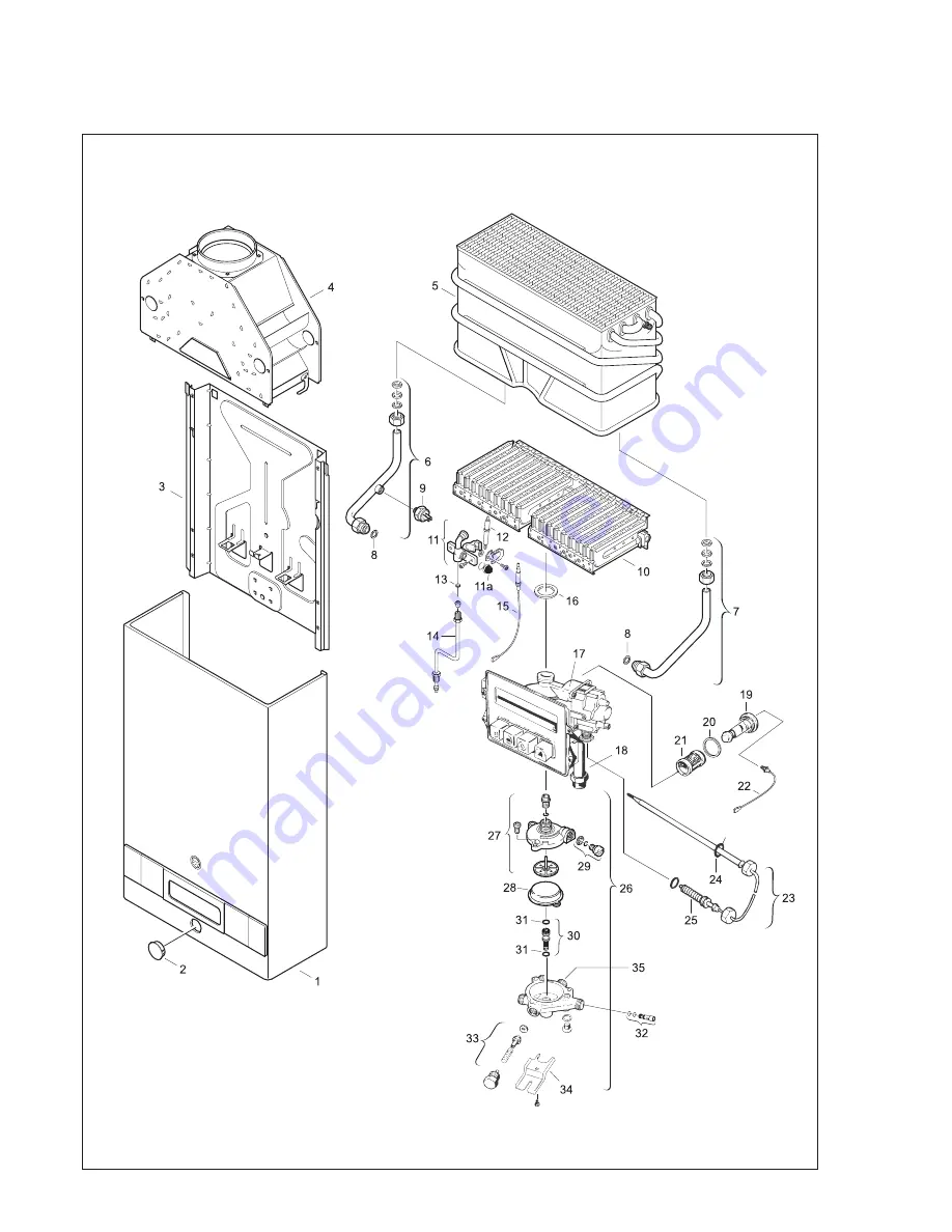
Fig. 11 - INTERIOR COMPONENTS DIAGRAM AND PARTS LIST
Page 1: ...pliance WHAT TO DO IF YOU SMELL GAS Do not try to light any appliance Do not touch any electrical switch do not use any phone in your building Immediately call your gas supplier from a neighbor s phon...
Page 2: ...gy efficiency Automatic Thermostatic Control for steady hot water temperature Input BTU s modulate to zero to prevent overheating of water from pre heat source Safety thermocouple at pilot burner Auto...
Page 3: ...S FROM COMBUSTIBLE AND NON COMBUSTIBLE MATERIALS FOR ALCOVE INSTALLATIONS FRONT VIEW SIDE VIEW AQUASTAR MODELS 125B 125BL 125BS 125X MODEL 125B 125B LOW PRESSURE 125B SOLAR 125X TOP A 12 FRONT B OPEN...
Page 4: ...anada The Installation should conform with CGA B149 1 2 INSTALLATION CODES and or local installation codes 2 Carefully plan where you install the heater Correct combustion air supply and flue pipe ins...
Page 5: ...the building 2000 Btu hr if all air is taken from the outside by horizontal ducts 4000 Btu hr if all air is taken from the outside by direct openings or vertical ducts Louvers grills and screens have...
Page 6: ...vent pipe connectors require a 6 inch clearance from combustibles National Fuel Gas Code specifies double wall Type B vent pipe be used in cold climates and for gas vents running through attics We co...
Page 7: ...ency malfunction of the supply system the gas valve and regulator must be checked for safe operation Make sure that the regulator vent is protected against blockage Vent blockage could occur during ic...
Page 8: ...adily accessible for servicing or replacement and be mounted as close to the water heater as possible See Fig 6 To install the PRV a suitable fitting connected to an extension on a T fitting can be sw...
Page 9: ...me and should resemble the diagram in Fig 8 If the flame is yellow or if the pilot knob has to remain depressed for a long time in order to keep the pilot lighted the pilot burner and or the pilot bur...
Page 10: ...coils should be flushed with a descaling solution Consult your dealer or Controlled Energy for instructions pulled off washed and blown out The pilot orifice has likewise to be cleaned or exchanged C...
Page 11: ...er valve assembly components need to be replaced immediately Note Water valve for model 125B S is part 8707002380 for both LP and NG models Contact service person to clean water valve or replace if co...
Page 12: ...at the tap the lower hot water pressure may be overpowered by a much higher cold water pressure which may cause the Aquastar burners to shut down Make sure faucet aerators or shower heads are free of...
Page 13: ...7 9 1 Heat exchanger 2 Pilot assembly 3 Burner manifold gas pressure test nipple 4 Main gas burner 5 Pilot gas tubing 6 Gas valve 7 Piezo igniter 8 Location of pressure tap screw 9 Water valve 10 Gas...
Page 14: ...14 AQ 125 BS Fig 11 INTERIOR COMPONENTS DIAGRAM AND PARTS LIST...
Page 15: ...lot Tube 8 700 707 316 15 Thermocouple 8 747 202 083 16 Burner assembly washer 8 710 103 060 17 Gas valve LP 8 707 011 467 Gas valve NG 8 707 011 469 18 Gas supply pipe 8 700 705 464 19 Electromagnet...
Page 16: ...ight Minimum Diameter Minimum Height 5 inches 6 feet NOTE Vent size must not be restricted Installation must comply with national fuel gas code venting requirements for a 117 000 Btu Category I applia...