13
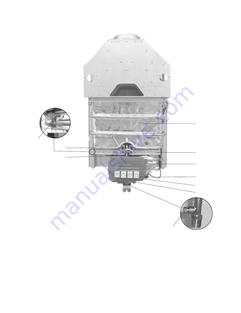
Fig. 10 - Diagram of AquaStar 125 B”S”
5
1
4
7
9
1.
Heat exchanger
2.
Pilot assembly
3.
Burner manifold gas
pressure test nipple
4.
Main gas burner
5.
Pilot gas tubing
6.
Gas valve
7.
Piezo igniter
8.
Location of pressure tap
screw
9.
Water valve
10.
Gas inlet gas pressure
test nipple
3
10
6
2
8


