


Get more information about the counting process:
It is possible to get more information about the counting. The counter will remember the 15 latest
counting operations. The Registration Unit(s) does not need to be connected in order to access the
information.
The display shows:
where x is 1 or the channel number of the first connected Registration Unit.
At this point special commands may be given. When the
Delete
key is pressed at the start of the
Weight a
?
is displayed. The next character will overwrite the
?
. If
Delete
is pressed again, the
?
will
disappear.
Page 8 of 20
Menu
is entered in order to start the menu system.
Top level menu
:
1
selects the Clock menu,
2
selects Parameters menu,
3
selects Results menu,
Stop
leaves the menu system.
Clock menu
Clock menu, date submenu:
Yes
selects date adjustment.
No
or
Stop
continues to time of day submenu.
If
Yes
is selected the month is first set by two digits and
Enter
, then day in month, and finally year is
set with four digits. When date is set the operator should select
No
or
Stop
to enter the time of day
submenu.
Clock menu, time of day submenu:
Yes
selects time of day adjustment.
No
or
Stop
goes back to top level menu.
If
Yes
is selected the hour is first set by two digits and
Enter
, then minutes, and finally seconds is set
by two digits. When the time is correct the operator should select
No
or
Stop
in order to go back to
top level menu.
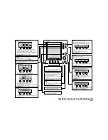
Parameters menu
:
WEIGHT(g) C
x
:
WEIGHT(g) C
x
:
1:Clock 3:Results
2:Params
Date:05-15-2006 New?
Time: 09:44:13 New?
1:New WGF 2:New CTF
C1: 1000 1000
1
selects new weight factor (WGF) for displayed channel
2
selects new count factor (CTF) for displayed channel
>
and
<
displays next and previous channel.
Stop
goes back
to top level menu.
The Weight factor is used to adjust the displayed weight.
The Weight factor will be limited to values from 500 to 2000 (-50 %, +100 %), and may be adjusted
for each channel.
A value of 1000 means no weight adjustment.
If the Weight factor for C1 is set to 500 the displayed weight for C1 will be one half of the value
compared to if the weight factor was 1000. In the same manner, if the weight factor for C2 is set to
2000 the displayed weight for C2 will be twice the value displayed if the weight factor was 1000.
Calculated weight factors should be rounded to closest integer.
Summary of Contents for CSE Series
Page 19: ...Page 19 of 20...
Page 20: ...Page 20 of 20...