GENERAL TECHNICAL INFORMATION
2 - 29
PEGASO 650
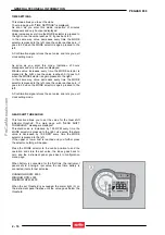
Trip time
Trip time value is calculated since last trip meter reset. This
calculation also includes stops (zero speed and engine
running) while does not include intervals with key-on and
engine off. Count stops with engine off.
The value is indicated in the display in [hh:mm] format, with
[TIME] written before. Saturation occurs from 99:59 to 00:00.
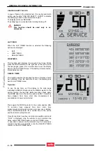
Maximum speed
Maximum speed is calculated since last reset. The value is
shown on the display with [nnn] format, with [MAX] written
before and the unit of measurement [km/h] or [MPH]
indicated after it.
Speed value is stored only if it stays the same for at least 3
samplings taken at intervals of 0.5 seconds.
I.e., given Vn, Vn+1, Vn+2
If (Vn<= Vn+1) & (Vn<=Vn+2) then VMAX= Vn
Battery voltage
This function measures battery voltage. The value is shown
in the display with [
nn.n
] format, the battery icon precedes
the value and the unit of measurement [
V
] follows the value.
•
Range:
9.0
÷
16.0
[V]. If voltage is lower than 9V or
higher than 16V, accuracy might exceed required
tolerances but should have a constant increasing trend.
•
Accuracy:
±
0.2V
with respect to voltage at the battery
(correction factors should then be added, as per table,
varying according to the vehicle the instrument is fitted
to).
Refresh: every 10 secs. To avoid indication oscillation, a
suitable software damping should be set.
Safety logic
Immobilizer and safety logic actuation are performed through
the
CONTACT
1 and
CONTACT
2 signals from the instrument
panel and should be closed to enable ignition. Immobilisation
is performed by opening all contacts.
Vehicle is immobilised maintaining at high logic level (open
contacts)
CONTACT
1 and
CONTACT
2 signals and at low logic
level (open contact) the S
TARTER RELAY ACTUATION
signal.
Safety devices are released setting at low logic level (closed
contact)
CONTACT
1 and
CONTACT
2 signals and at high logic
level (closed contact) the S
TARTER RELAY ACTUATION
signal.
Summary of Contents for Pegaso 650 2005
Page 1: ...INTRODUCTION 0 1 PEGASO 650 INTRODUCTION 0 ProCarManuals com ...
Page 7: ...GENERAL INFORMATION 1 1 PEGASO 650 GENERAL INFORMATION 1 ProCarManuals com ...
Page 71: ...FUEL SYSTEM 3 1 PEGASO 650 FUEL SYSTEM 3 ProCarManuals com ...
Page 78: ...ENGINE 4 1 PEGASO 650 ENGINE 4 ProCarManuals com ...
Page 96: ...ENGINE 4 19 PEGASO 650 Bend the safety washer Refit the guide plate ProCarManuals com ...
Page 105: ...CYCLE PARTS 5 1 PEGASO 650 CYCLE PARTS 5 ProCarManuals com ...
Page 124: ...CYCLE PARTS 5 20 PEGASO 650 Remove the shim Remove the top sliding bush ProCarManuals com ...
Page 131: ...WIRING DIAGRAM 6 1 PEGASO 650 WIRING DIAGRAM 6 ProCarManuals com ...
Page 138: ...WIRING DIAGRAM 6 8 PEGASO 650 6 1 2 WIRING DIAGRAM ProCarManuals com ...


