background image

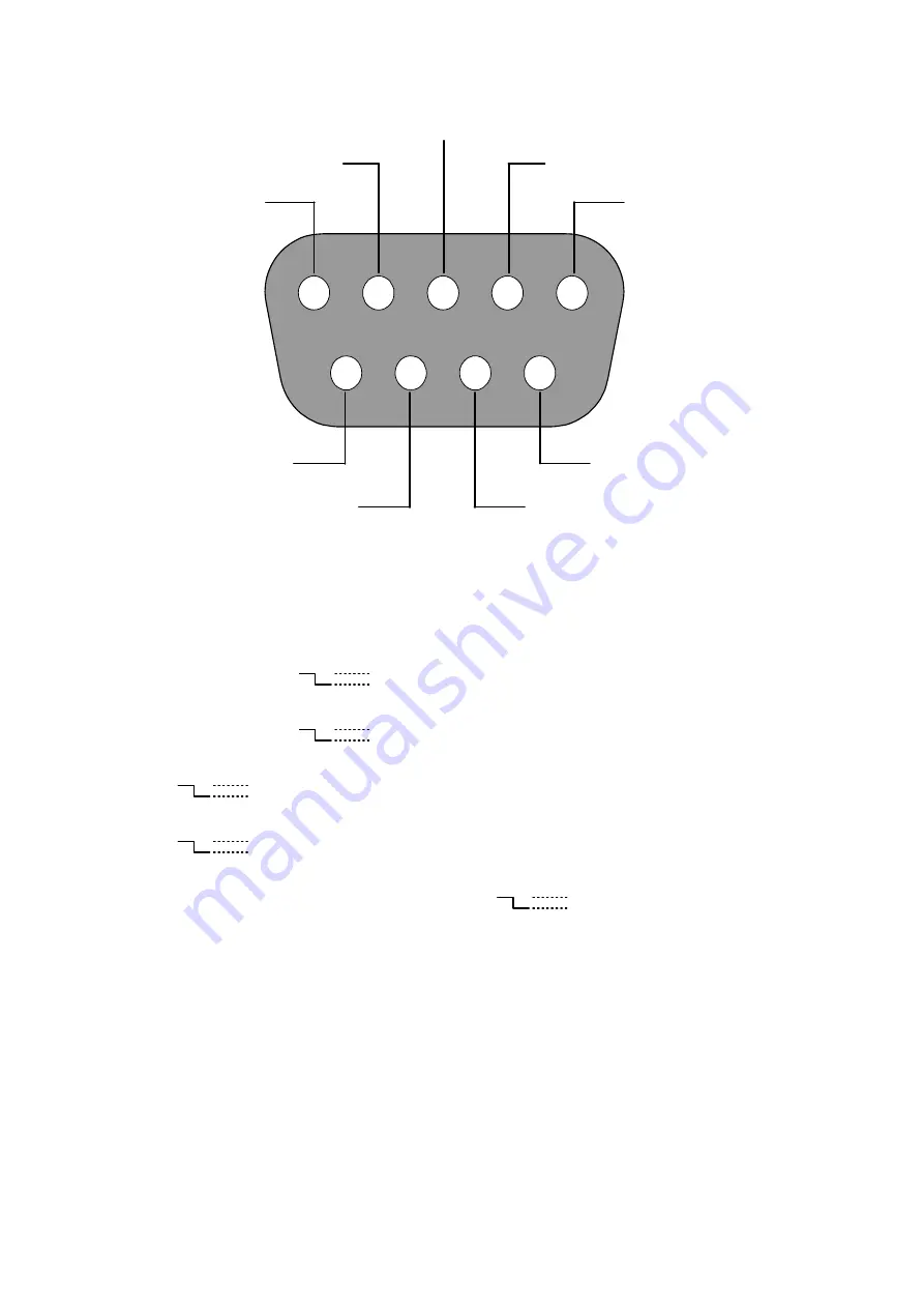
2.3 ALARM In/Out 

ALARM1 IN

ALARM4 IN

ALARM2 IN

ALARM3 IN

ALARM OUT

RECORD IN

GROUND

DISK FULL

ALARM RESET

1

2

3

4

5

6

7

8

9


THE ABOVE FIGURE IS A REAR VIEW. 

1. GND: 

Ground Contact.


2. ALARM OUT (OUTPUT): 

This is an alarm-output trigger. Connect this to external devices such as 

buzzers or lights. (

5V

0V(Active)

)


3. DISK FULL (OUTPUT): 

This is a disk-full output trigger. Connect this to external devices such as 

buzzers or lights. (

5V

0V(Active)

)


4. ALARM  RESET  (INPUT): 

This pin connects to an alarm-clear device for clearing an alarm.


(

5V

0V(Active)

)


5. RECORD IN (INPUT):

 This pin connects to a record-triggering device for starting a record. 

(

5V

0V(Active)

)


6. ALARM4 IN (INPUT): 

This is an alarm input( for CH 4 )which can be programmed in the menu 

system to Normally Open or Normally Closed. (

5V

0V(Active)

)


7. ALARM3 IN (INPUT): 

same as the above, for CH 3


8. ALARM2 IN (INPUT):

 same as the above, for CH 2


9. ALARM1 IN (INPUT): 

same as the above, for CH 1


10

Summary of Contents for DVR-3704

Page 1: ...Before trying to connect or operate this product please read this manual completely INSTALLATION OPERATION MANUAL Digital Video Recorder DVR 3704 ...

Page 2: ......

Page 3: ...her model of DVR for you will lose the data you have stored in the hard disk s if you do so You are free to use the same hard disks between DVRs belonging to a single model Danger of explosion if the Lithium battery RTC Battery is incorrectly replaced Danger of explosion if battery is incorrectly replaced Replace only with the same or equivalent type recommended by the manufacturer Dispose of used...

Page 4: ... 3 Timer Recording 3 2 PLAYBACK OPERATIONS 13 13 3 2 1 Fast Forward Reverse 13 3 2 2 Playback Picture by picture 3 3 BACKUP OPERATIONS 14 3 4 KEY LOCK OPERATIONS 15 3 5 TRIPLEX OPERATIONS 15 4 SEARCH MODE 16 4 1 RECORD LIST 16 4 2 ALARM LIST 16 4 3 TIME FILTER 17 5 MENU MODE 18 5 1 QUICK SETTING 19 5 2 DISPLAY OPTION 20 5 3 SEQUENCE SETTING 21 5 4 ADJUST PICTURE 21 5 5 ADVANCED SETTING 22 22 5 5 1...

Page 5: ...ER INTRODUCTION 30 7 1 TCP IP COMMUNICATION SETUP 30 7 2 CONNECTION TESTING 33 7 3 SOFTWARE INSTALLATION 34 7 4 VIEW THE DVR VIDEO FROM A REMOTE PC 37 7 5 OPERATION 39 8 SPECIFICATIONS 42 APPENDIX 1 Insert the mobile rack 43 APPENDIX 2 RS 232 Connection 44 APPENDIX 3 Compatible hard disk drives 45 3 ...

Page 6: ...B device which you can transfer to your PC to play and print out Our digital video recorder further supports the network function in which you can use a remote PC to connect with the DVR and retrieve vital images from a hard disk You will be able to access both video and audio records effortlessly Use our device to bring your total environment under your complete surveillance archiving and control...

Page 7: ...n USB connector to save image s for an individual channel to an USB device 4 BNC video input channels 4 alarm inputs and 1 alarm output Audio recording Quick setup menu Disk full warning Supports factory default menu setting Supports Play Reverse Play Pause Stop FF REW for playback 5 ...

Page 8: ...ive and play modes press twice successively to get two multi channel modes on the main monitor the first time in a 4 way vision and the last in a 9 way mode 6 Exit PIP button Press to exit the menu setup mode The button is used to select video modes and video channels In the Live Record mode press this button to loop the picture in picture modes in turns Note Press the button for at least 3 second...

Page 9: ...rection at faster speeds than the recorded speed and the LED will emit green light During the freeze press to display one image of a picture at a time in the backward direction 14 button Press to play a recorded video in the forward direction at faster speeds than the recorded speed and the LED will emit green light During the freeze press to display one image of a picture at a time in the forward...

Page 10: ...at least 3 seconds to switch off Press again to activate the device 21 disk Indicator The indicator shows the operation status of the unit s hard disk drives The green light indicates the hard disk drive is storing or retrieving data 22 USB port This is used for system software updating and archiving accessing critical images Note When turning on the DVR a message of SYSTEM INITIALIZING will appea...

Page 11: ...nected to the video loop through the connector Set the impedance to the 75Ω position if no other device is connected to the corresponding loop through the connector The default setting is 75 Ω 5 Video in connectors Ch1 Ch4 Video loop through connectors Ch1 Ch4 These 4 BNC connectors are used to connect to the video output from the cameras 4 cameras can be connected to these connectors These 4 BNC ...

Page 12: ...er Connect this to external devices such as buzzers or lights 5V 0V Active 4 ALARM RESET INPUT This pin connects to an alarm clear device for clearing an alarm 5V 0V Active 5 RECORD IN INPUT This pin connects to a record triggering device for starting a record 5V 0V Active 6 ALARM4 IN INPUT This is an alarm input for CH 4 which can be programmed in the menu system to Normally Open or Normally Clos...

Page 13: ...e the following steps to activate the programmed alarm recording For ALARM settings please refer to section 5 5 1 for more details 1 Press the MENU button to enter the MAIN MENU 2 Select the ADVANCED SETTING and press the Enter button to enter the ADVANCED SETTING page 3 Select the ALARM SETTING and press the Enter button to enter the ALARM SETTING page Please refer to section 5 5 1 for more infor...

Page 14: ...ing Set the time to end a recording NOTE You can set each time period between 00 00 and 23 59 24HR mode 6 If you want to stop recording in a scheduled recording session or at anytime you can press the button for at least 3 seconds NOTE You can proceed to start the scheduled recording from the current time if it is in the scheduled interlude as soon as the setting is complete and come out from the ...

Page 15: ...deo in the forward direction at a speed faster than the recorded speed Press the button to increase the forward rate as 2x 4x 8x or 16x Reverse Press the button to view the recorded video in the reverse direction at a speed faster than the recorded speed Press the button to increase the forward rate as 2x 4x 8x or 16x Normal Press the or button to return to the normal speed of playback 3 2 2 Playb...

Page 16: ...in the multi channel display mode the user can choose the multi channel image s he likes and then archives it USB image How many pictures can be stored depends on the capacity of the USB device The image is stored in the DVR format You can have the saved images shown by our Network Viewer software If more than one clip is stored in a USB device file names will be assigned in sequence as shown belo...

Page 17: ...k function Press the v button for at least 3 seconds to deactivate the key lock function The device will emit a beeping sound signal and show the message of KEY UNLOCK 3 5 TRIPLEX OPERATIONS The Live Play and Record modes act simultaneously to comprise the Triplex function The three modes played together comprise the Triplex function CH1 CH2 CH3 CH4 CH1 CH2 CH3 CH4 08 25 2006 06 27 20 08 24 2006 0...

Page 18: ... 2006 14 25 08 14 2006 19 22 08 14 2006 19 25 08 14 2006 09 30 08 14 2006 16 30 08 13 2006 11 00 08 13 2006 18 00 08 12 2006 15 00 08 12 2006 17 20 08 12 2006 08 03 08 12 2006 14 25 08 10 2006 07 30 08 10 2006 16 05 08 09 2006 10 10 08 09 2006 15 25 08 08 2006 09 10 08 08 2006 14 30 08 07 2006 08 13 08 07 2006 10 25 ZOOM KEY SWICTH HDD NOTE The maximum number of lists for one HDD is 1000 4 2 ALARM...

Page 19: ...the following steps to proceed with the time list search function 1 Press the Search button to enter the search mode 2 Select the TIME FILTER and press the Enter button to access the TIME FILTER page 3 Set the date time period you wish to search for the recorded video 4 Press the Enter button to search and play the recorded video 5 If no video is found please return to the TIME FILTER page and rep...

Page 20: ...s within the menu setup mode are described in the paragraphs below MAIN MENU 1 QUICK SETTING ENTER 2 DISPLAY OPTION ENTER 3 SEQUENCE SETTING ENTER 4 PICTURE ADJUST ENTER 5 ADVANCED SETTING ENTER 6 DISK SETUP ENTER 7 SYSTEM SETTING ENTER KEY FUNCTIONS MENU button Press to enter the MAIN MENU page You can also use this button to return directly to the MAIN MENU page from any other page After returni...

Page 21: ...e any changes For example you can fix channel 1 from the default setting CAM 1 to CH1 EXIT 4 RECORD RATE Select this item and use the and v buttons to adjust your recording rate out of our available rate from 1 2 3 5 10 15 30 and 60 NTSC or 1 2 3 5 8 12 25 and 50 PAL 5 RECORD QUALITY Choose the quality out of a quality range from BASIC STANDARD and HIGH to BEST 6 RESOLUTION This option determines ...

Page 22: ...he system time here 2 DATE SETTING You can set the system date here 3 DATE MODE Gives a date in terms of months days or years in the following 3 alternative formats DD MM YYYY YYYY MM DD and MM DD YYYY 4 TITLE SETTING Fixes a desired title within 8 characters for each channel Please choose the particular channel s title then press the Enter button and use the and v buttons to make any changes For ...

Page 23: ...M SETTING ENTER Please choose the item and then use the and v buttons to make any changes Note In the Live Record mode press the button to start the sequence display mode then loop back and the icon will show on the screen simultaneously 5 4 ADJUST PICTURE This page enables you to position your images the way you desire You can use the and v buttons to adjust the BRI brightness and CON contrast pr...

Page 24: ... ENTER 4 DISK FULL REWRITE 5 SCHEDULE SETTING ENTER 5 AUDIO ON 1 RECORD RATE Select this item and use the and v buttons to adjust your recording rate out of our available rates of 1 2 3 5 10 15 30 and 60 NTSC or 1 2 3 5 8 12 25 and 50 PAL 2 RECORD QUALITY You can choose quality at 4 different levels of recording images from BASIC STANDARD and HIGH to BEST 3 RESOLUTION This option determines the re...

Page 25: ...ENTER 5 SCHEDULE SETTING ENTER 1 ALARM INPUT Select and set each channel to activate ON or deactivate OFF the three modes of SENSOR V VIDEO LOSS and MOTION SENSOR An alarm is triggered when the sensor is touched V LOSS An alarm occurs when video is lost MOTION Alarms which are activated while the motion detection function is operating 2 ALARM DURATION Choose a particular duration period to set off...

Page 26: ...ITIVITY Control the sensitivity of the motion detection function Use the and v buttons to select the sensitivity from 1 HIGHEST 2 HIGH 3 NORMAL 4 LOW to 5 LOWEST for each channel MOTION CHECKING The alarm input in each channel can be set from 0 to 15 images Once motion detection occurs the numbers of images you set the device will emit an alarm 2 DETECT ZONE MOTION SETTING 1 SENSITIVITY MOTION CHE...

Page 27: ...9 2 PORT DATA CMD The option is to set the transfer ports of the image data and command data Note The values of DATA CMD ports must be the same with the setting of the Network Viewer software refer to chapter 7 3 IP ADDRESS The IP address may be manually edited 4 SUBNET MASK The IP mask may be manually edited 5 GATEWAY The gateway may be manually edited NOTE When only one unit of the DVR is connec...

Page 28: ...network address If you have any questions regarding these settings please contact a qualified MIS professional or your ISP 5 5 5 SCHEDULE SETTING Enter the setting to set up 7 forms of schedules Use the or v button to choose ON ENABLE or OFF DISABLE for each schedule SCHEDULE SETTING START STOP 1 SUN OFF 00 00 12 00 2 MON OFF 00 00 12 00 3 TUE OFF 00 00 12 00 4 WED OFF 00 00 12 00 5 THU OFF 00 00 ...

Page 29: ...TER 7 SYSTEM SETTING ENTER 1 HDD REFORMAT This option allows you to clear out all the data in the HDD After entering the item a message of FORMAT HDD will appear If you want to format the HDD please select YES then press the Enter button 2 USB DEVICE INFO The DVR can be connected to a USB flash memory USB TOTLE SIZE You can find the USB device capacity here if the DVR connected with the USB device...

Page 30: ...s function when you enter the MAIN MENU the next time a message of CHECK MENU PASSWORD will appear Please enter the correct password then press the Enter button to enter the MAIN MENU 4 LOAD FACTORY SETTING If you want to execute the default setting shift the focus to this item and enter After entering the item a message of LOAD FACTORY SETTING will appear If you want to load the factory setting p...

Page 31: ...the alarm recording lists HDD REST TOTAL TIME Total 14 hours remaining time available Total 24 hours recording time available USB REST TOTAL TIME Total 620 MB rest capacity of memory available Total 978 MB memory capacity available Press the Display button again the unit will display the information as shown in Figure 6B below Figure 6B RECORD MODE Shows the mode of recording STOP MANUAL TIMER ALA...

Page 32: ...Pentium III 750MHz at least 2 128 MB RAM 3 Windows 2000 XP or above 4 4 MB Video card capable of 24 bit true color display 5 160 MB free hard disk space for software installation 6 10 base T network for LAN operation 7 1 TCP IP COMMUNICATION SETUP Follow the instructions below to install the TCP IP communication program into your computer 1 Click the Start Menu from your computer and point to the ...

Page 33: ...figuration tag check if the TCP IC is included in the network components list If the TCP IP is included please process step 5 If it is not included please follow step 4 to install the TCP IP 4 TCP IP installation During the installation you will be requested to insert the windows XP CD ROM After installation the PC will be restarted 31 ...

Page 34: ...vider If you are using a DHCP server please select Obtain an IP address automatically Any assigned IP address for the connected DVRs must be in the same class type as the server If there is no DHCP server please select a specific IP address and type in the IP address of your PC This IP address must be different from the DVR IP but in the same class type Note The IP address of a DVR in a network mu...

Page 35: ... is the DVR IP address that is assigned for the connected DVR 3 If you receive a response as in the sample screen below the connection hasn t been successfully established Please re check all the hardware and software installations by repeating steps 1 to 5 If you still can t establish the connection after rechecking please contact your dealer 4 If you receive a response as in the sample screen be...

Page 36: ... the CD ROM device It ll automatically enter the Network Viewer installation screen Please see the screen below Note Please choose the Next button to continue Step 3 The installation screen will show the message C Program Files Network Viewer Or you can select the path you want Note Click Next to continue the installation 34 ...

Page 37: ...tion screen will show the message Network viewer Or you can enter the folder name you want Note Click Next to continue the installation Step 5 Tick to create a desktop icon Note Click Next to continue the installation 35 ...

Page 38: ... to complete the installation process Step 8 After completing installation you can double click the file shown below Or click the Start Menu in the computer and select Programs to open the Network Viewer page Then click the Network Viewer tag to start the program Note Please make sure the TCP IP communication software has been properly set and configured in your computer 36 ...

Page 39: ...Viewer a connection box will appear as follows The default multi screen is the 16 channel mode Step 1 Press the button to enter the Network Viewer Setting window which is shown below Step 2 Please enter your DVR s IP Address and key in the correct Data Command port values Note Please make sure the values of Data and Command ports which you enter are the same as given in with the NETWORK SETTING pa...

Page 40: ...default is 9999 then click the OK button Step 6 After entering the DVR you will see the videos of all the cameras as shown below Note To add more connections of other DVRs please repeat the above instructions Note It s necessary to remove the exit program when you are going to install a new version of Network Viewer Every time you update the Network Viewer the original version must be removed firs...

Page 41: ...w Select the IP address from the drop down list which you want to connect type the correct password and then press the OK button to connect Open the local files Press the button to open the recorded files in the disks 2 Note Select the recorded file dvr and then press the button to play it 39 ...

Page 42: ...ng back mode Screen divisions Choose any of the buttons you want 5 Multi screen The videos of all the cameras are displayed here 6 Scroll bar and function keys Click each of these buttons to execute its functions 7 Click Yes to start recording DVR recording control Press the button to start to record or to stop recording While recording the icon will become yellow in color In the non recording mod...

Page 43: ... image of the chosen channel You can set the backup file path and the file name Save all images Click to save four JPG images of 4 channels You can set the backup file path and the file name 10 Print single channel image Click the Print CamNo XX Image button to enter the Print image page Click Print to start the printing Click Close to cancel Reset single channel Reload the signal of the channel R...

Page 44: ...arm Circular Timer Alarm Recording Pre Alarm Post Alarm Pre alarm Recording 30 images Fast Forward 2X 4X 8X 16X Playback Speeds Reverse 1X 2X 4X 8X 16X Image Stepping Search Time Filter Alarm List Record List Zoom 2X Digital Zoom Motion Detection 5 level sensitivity control 8 x 6 motion area set up OSD Cam Title Time Date Mode Error Message Alarm In Out 4 Alarm Inputs 1 Alarm Outputs Built in Buzz...

Page 45: ...ng screw 1 in the mobile rack Ⅰ of the DVR and detach it Step 2 Draw out the mobile rack Ⅰ from the DVR Step 3 Insert the mobile rack Ⅱ in the device and screw in screws 2 Step 4 Insert the mobile rack Ⅰ back in the device and screw in screw 1 Note Please attach the interface connector and the power connector to the drives The installation of the mobile rack is complete The mobile rack is a purcha...

Page 46: ...NNECTION The transmission protocol is 8 data bit 1 start bit 1 stop bit and no parity Five different speeds can be used 1200 baud per second 2400 baud 4800 baud 9600 baud and 19200 baud The default setting is 2400 baud per second 44 ...

Page 47: ... ST3500630A 500GB ST2500641A 500GB 6H500R0 500GB 6H400R0 400GB 5A300J0 300GB 6L250R0 250GB 7Y250P0 250GB Maxtor 6B200P0 200GB 6Y160P0 160GB 6Y120L0 120GB 6Y080L0 80GB 6E040L0 40GB SP4002H DOM 40GB SP1614N 160GB Samsung SV1604E 160GB SV0802N 80GB NOTE Hard disk drives not shown on this list have not been tested by our engineering team and are not recommended for use with this product For the latest...

Reviews: