background image

Installation and Service Manual – Under-the-Counter Point of Use 5 Stage Reverse Osmosis System with Booster Pump 


Copyright © 2014 Applied Membranes, Inc.  

All Rights Reserved.


Page 18 


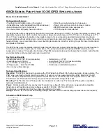
6800 Series Pump (for 10-36 GPD) Specifications 

M

ODEL 

N

O

:


6840-2J03-B221 

Distinguishing Features: 

• Toughest, most durable pump on the market


• More flow at extremely low inlet pressures


• Adjustable max. outlet psi(regardless of feed pressure)


• New motor venting system to remove moisture


• Expels trapped air (no more air locks) 

• EMI/RFI electronic noise suppression


• Can be mounted with pump head up or down 

• 100% final performance tested


The 6800 series pump is intended for use with RO membranes rated up to 50 GPD. The pump incorporates a unique, fully 
adjustable, by-pass valve which controls the maximum allowable outlet pressure (70 to 110 psi, or a fixed by-pass of 70, 
90, or 110 psi. regardless of variation in feed water pressure. Its new innovative patented design allows mounting in 
several positions without entrapping air, including pump head down and pump head up. Close tolerances within the pump 
head and motor, give a lower amp draw; lower operating temperatures; smoother running; longer life; lower maintenance; 
and greater efficiencies. 
 
The 6800 series pump incorporates powder coated die cast alloy and a unique label sealing process to reduce exposure 
to moisture which is the major cause of motor failure. The pump is available with optional EMI/RFI electronic noise 
suppression to reduce TV reception interference. The 6800 series pump is capable of operating in a warm, humid hostile 
environment where other pumps have been known to fail.  
 

Key Optional Benefits: 

• Boosts pressure 40 to 120 psi (adjustable)


• Self-priming –– 60" lift


• Fixed pressures to 160 psi


• Low voltage (12-24V) for maximum safety


• Up to 30,000+ operating hours 

• Corrosion resistant exterior


• Whisper quiet –– less than 45 DBA 

• Continuous or intermittent operation


• Can run dry without damage 


Technical Specifications:


Operation:  

The 6800 is designed to operate with a PSW tank shut-off switch for hydro-pneumatic storage systems. The 

PSW, when used with a typical under-the-counter R.O. system, can be augmented with an ESO, Electronic Shut-off 
Valve. It is also compatible with most hydraulic shut-off valves. For counter-top systems, Aquatec's TLC, Tank Level 
Controllers, shut off feed water and the pump when the product water storage tank is full. 

Mounting:  

The "flexible or steel" base plates are included at no extra cost. The "Universal" base plate is available 

optionally at additional cost. 

Power:  

Pumps operate with low energy (only 14 watts), low voltage (12-24 volt) motors, powered with compatible 

transformers with world wide primary voltages available (100 VAC, 120 VAC, 230 VAC).  
Transformers are optional and must be ordered in addition to the pump. 

Fittings:  

Built-in 1/4" John Guest half cartridge fittings eliminate need for external fittings (unless elbows are required) 


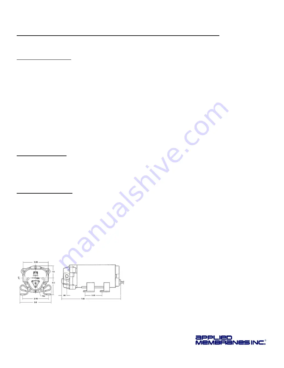
Schematic of 6800 Series Pump 


Summary of Contents for AAA-1005P

Page 1: ...or Installation Operation and Maintenance of 5 Stage Point of Use RO System with Feed Booster Pump System Flow Rate Model Number 12 Gallons Per Day AAA 125P 24 Gallons Per Day AAA 245P 36 Gallons Per Day AAA 365P System Flow Rate Model Number 50 Gallons Per Day AAA 505P 75 Gallons Per Day AAA 755P 100 Gallons Per Day AAA 1005P A three digit voltage code is added to the end of the model number Exam...

Page 2: ...be changed every three to six months depending on the quality of the feed water supply Conditions for Operation Source Water Supply Community Private Non Chlorinated or chlorinated as long as the carbon filter is in place and replaced every 6 months Membranes will be damaged by chlorine System Pressure 40 psi minimum 100 psi maximum Temperature 4º 38º C 40º 100º F Maximum Supply TDS Level 1500 ppm...

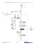
Page 3: ... 3 6 months 2nd Stage Carbon block pre filter Every 3 6 months 3rd Stage Carbon block pre filter Every 3 6 months 4th Stage Reverse osmosis membrane Every 12 months 5th Stage Post carbon filter Every 3 6 months Connection Location Tubing Color System Feed IN From feed line to fitting at the entrance of the first filter housing Blue Reject Water From the flow restrictor to the drain saddle Black Pr...

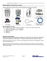
Page 4: ...m Variable speed drill with 7 16 drill bits and 7 16 open end wrenches or adjustable Phillips screwdriver Utility knife Teflon tape Check Location Determine the location for the installation of the RO system Avoid locations where the system might come in contact with hot water pipes or other hazards An electrical outlet is needed for the pump power supply Determine the location for the faucet Chec...

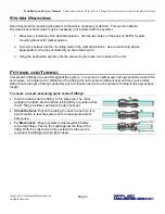
Page 5: ...ittings and Tubing Compression fittings are used throughout the system To ensure an optimal seal tubing should be cut with the end square An angled cut or distortion of the tubing will not provide an efficient seal and may cause leaks Determine the length of tubing needed for each connection and cut each segment of tubing to the appropriate length To ensure a secure seal using quick connect fittin...

Page 6: ...Installation and Service Manual Under the Counter Point of Use 5 Stage Reverse Osmosis System with Booster Pump Copyright 2014 Applied Membranes Inc All Rights Reserved Page 6 ...

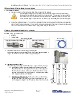
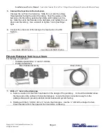
Page 7: ...d under the sink or if water continues to come out of the faucet turn off the main supply at the entry to the house Feed Adapter Installation For this step you will need o Wrench o Teflon Tape Feed Adapter Kit Blue Tubing Slip Joint Adapter with washer Ball Valve with nut 1 Install the ball valve into the slip joint adapter Wrap the threads on the ball valve with Teflon tape approximately 3 wraps ...

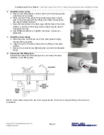
Page 8: ...nger tight 4 Connect the other end of the tubing to the feed port on the RO System Feed Valve OPEN Position Feed Valve CLOSED Position Drain Saddle Installation For this step you will need o Variable speed drill w and drill bits o Phillips Screwdriver Drain Saddle Assembly Black Tubing 1 Drill a hole in the drain pipe a Select a location for the drain hole based on the design of the plumbing It sh...

Page 9: ...e drain pipe with the hole in the drain saddle A drill bit or other long narrow object may be used to help align correctly d Use Phillips screwdriver to tighten the clamp Avoid over tightening 3 Install the drain tubing a Slide the black nut onto the end of the black plastic tubing threads facing outward b Insert the end of the black tubing into the fitting on the drain saddle c Secure the connect...

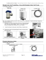
Page 10: ...s been factory charged and covered with a blue cap 1 Locate the in out port on the top top of the tank Wrap the threads with Teflon tape approximately 3 wraps Connect the tank ball valve by threading onto the fitting Do not over tighten 2 Insert the tubing into the quick connect fitting on the ball valve 3 Connect the other end of the tubing to the tee on the inlet of the post carbon filter Tank V...

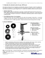
Page 11: ...proper cutting tools We strongly recommend the use of a Relton type device Follow the directions that accompany the tool carefully 2 Faucet Installation Above the Countertop 1 Small Rubber Washer 2 Metal Faucet Hole Cover 3 Large Rubber Washer Below the Countertop 4 Plastic Locating Washer 5 Metal Lock Washer 6 Securing Nut Installed in on tubing 7 Plastic Tubing Insert 8 Plastic Ferrule 9 Compres...

Page 12: ...rain lines are secure and free from leaks Slowly turn the feed valve counterclockwise until fully open the handle should be in line with the tubing as it enters the connection Check the stem seal for leakage If necessary tighten stem nut lightly Turn storage tank valve one quarter turn counterclockwise to open the valve the handle should be in line with the tubing as it enters the connection Open ...

Page 13: ...change is complete 1 Remove pre filters from filter housings Use a filter wrench if the housings are too tight 2 Discard used filters but save o rings for re use 3 Clean inside of all housings with a mild soap solution and then rinse with RO water 4 Lubricate the o ring and replace in filter housing 5 Insert the new filters into the appropriate housings and replace the housings onto the system 6 D...

Page 14: ...r well water etc for pressure A booster pump may be required Change in feedwater temperature The reverse osmosis membrane used in your unit is rated at 77ºF and 60psi Water production will decrease approximately 1 5 for each degree that your incoming water is below 77ºF It may be necessary to change to a higher flow membrane and flow restrictor Storage tank pressure is too low Check pressure with ...

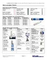
Page 15: ... AAA 1005 M T1812A100 H R1000QC Other Replacement Components Part Description Image H H14FWW33 Filter Housing White OR H10F O Ring for Filter Housing PV2012PME Membrane Housing H S4010ANW Storage Tank White 4 4 Gallon 3 2 Gal Usable Bladder Tank H J2021KW Clip Membrane Housing to Inline Filter H J2025PW Membrane Housing Clip Part Description Image H T5019 Faucet Non Airgap Long Reach Chrome H V105...

Page 16: ...ut If the transformer is not functioning properly its current capacity may have been exceeded Replacement may be necessary b If the transformer is properly sized and is delivering the correct voltage to the system remove the holding tank pressure switch PSW from the system by disengaging both connectors and connecting the pump directly to the transformer i If the pump now runs the pressure switch ...

Page 17: ...ell as water entering the motor from an external source c Squeaking may be associated with the by pass mechanism brush contact with the commutator surface or inadequate lubrication in the rear bearing Consult the factory 4 The pump is causing electrical noise interference a Try locating the pump on a dedicated electrical circuit separate from the device that is being interfered with b Consult fact...

Page 18: ...ause of motor failure The pump is available with optional EMI RFI electronic noise suppression to reduce TV reception interference The 6800 series pump is capable of operating in a warm humid hostile environment where other pumps have been known to fail Key Optional Benefits Boosts pressure 40 to 120 psi adjustable Self priming 60 lift Fixed pressures to 160 psi Low voltage 12 24V for maximum safe...

Page 19: ...down Self priming 60 inch lift Improved venting system removes moisture Corrosion resistant exterior Designed for 15 000 operating hours Outlet pressures up to 160 PSI Extremely quiet operation less than 52 DBA Runs dry without damage Low voltage 12 24V for maximum safety Power The 8800 Series pumps operate safely with low energy 24 watts low voltage 12 24V motors They can be used with compatible ...

Page 20: ...not be liable for damages or delay caused by defective material Products returned to SELLER for warranty examination must be shipped freight prepaid SELLER S Liability SELLER SHALL NOT BE LIABLE FOR PROSPECTIVE PROFITS OR SPECIAL INDIRECT OR CONSEQUENTIAL DAMAGES NOR SHALL RECOVERY OF ANY KIND AGAINST SELLER BE GREATER IN AMOUNT THAT THE PURCHASE PRICE OF THE SPECIFIC GOODS SOLD AND CAUSING THE AL...

Reviews: