Installation and Service Manual – Under-the-Counter Point of Use 5 Stage Reverse Osmosis System with Booster Pump
Copyright © 2014 Applied Membranes, Inc.
All Rights Reserved.
Page 11
1. Determine the desired location for your RO Faucet
The product water faucet may be installed on any flat surface at least 2” in diameter. Check the underside of
the location for interference. The standard faucet that is supplied with the system requires a ½” diameter hole.
The optional air-gap faucet requires a larger hole of ¾” to allow for the additional tubing connections required.
Stainless Steel Sinks
Begin by placing a piece of masking tape or duct tape on the determined location where the hole is to be
drilled. Make a small indent to mark the desired drilling location using a center punch. Drill a pilot hole with
a
⅛
” metal drill bit. Enlarge the hole using a ¼” metal drill bit, using factory approved method or approved
plumbing practice.
Porcelain/Enamel Sinks or Tile Countertop
Sinks of this type are very easy to damage due to the nature of the materials of construction. A successful
installation into these sinks requires a knowledgeable technician with the proper cutting tools. We strongly
recommend the use of a “Relton” type device. Follow the directions that accompany the tool carefully.
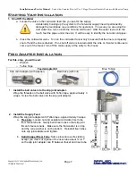
2. Faucet Installation
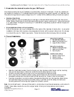
Above the Countertop
1. Small Rubber Washer
2. Metal Faucet Hole Cover
3. Large Rubber Washer
Below the Countertop
4. Plastic Locating Washer
5. Metal Lock Washer
6. Securing Nut
Installed in/on tubing:
7. Plastic Tubing Insert
8. Plastic Ferrule
9. Compression Nut
Slide the small rubber washer, then the metal cover, then the large rubber faucet over the mounting
tube onto the faucet base, in that order so that the small rubber washer is on top.
Insert the mounting tube into the hole in the sink and position the faucet correctly.
From under the sink, install the plastic locating washer followed by the metal lock washer onto the
threaded mounting tube, and secure them with the securing nut. Screw on the nut and tighten.
Feed the compression nut onto the tubing, threaded side facing the end, then feed the plastic ferrule
and install the tubing insert into the end of the tubing. Insert the end of the tubing into the faucet
mounting tube as far as it will go then tighten the nut with a wrench.
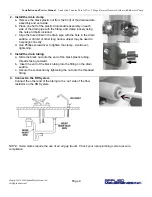
Note:
Non-Air Gap Faucet – Comes with the system. (Air Gap may be purchased separately - part number H-
T5022.) Some states require the use of an air gap faucet. Check your local plumbing code to assure
compliance.


