– 28 –
Setting the Main Flame
IMPORTANT: When the Flame Safeguard relay module
is switched to the TEST mode, it stops and holds at
the next Run/Test Switch point in the operating
sequence. Make sure that the Run/Test Switch is in
the RUN position before starting the burner.
CAUTION: Do not attempt to start the burner when
furnace is full of vapor or combustion chamber is
very hot.
CAUTION: At no time should you stand in front of
the relief door.
Connect the test instruments, meters, and thermometers
on the heater and controls to measure and record the
appropriate data.
Install one manometer at test port on the last tee of the
burner manifold and one at the relief door.
With all the safeties made, this will energize Burner
Relay (RE-02) and burner will light. The I/O Zone 583
Controller (UC-01) will send a 0 to 10 VDC signal to the
Interface Module (IM-02) located inside the Modulating
Gas Valve Operator (MT-11). See check out procedure
for (IM-02). At approximately 0 VDC the valve will be in
low fi re and 10 VDC is high fi re. Prior to setting low and
high fi re you should have your test equipment installed
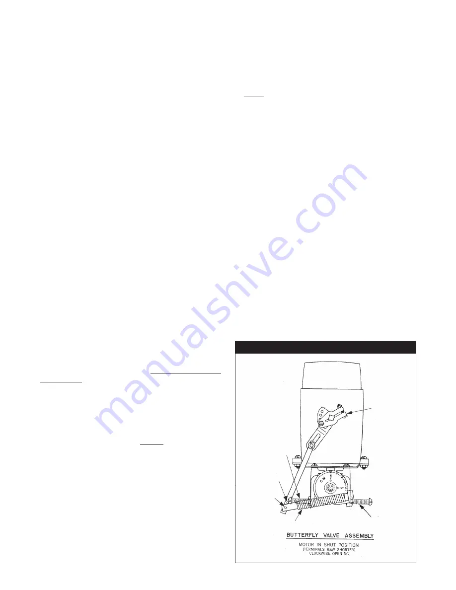
and be familiar with the Butterfl y Valve (GP-39) and its
adjustment. For the high fi re setpoint, refer to the unit
rating plate for Normal Manifold Pressure in inches
of W.C. With the Modulating Gas Valve Operator (MT-
11) in its high fi re position set high fi re using the Main
Gas Pressure Regulator (GP-05) and with the high fi re
adjusting screw on the Butterfl y Valve (GP-39). Remove
the + or – wire from (IM-02) and set low fi re with the low
fi re adjusting screw on (GP-39). See fi nal checks and
adjustments. Cycle the pilot and burner several times to
be sure it lights off reliably.
Enable the fans and heat as described earlier in this
section.
Restart unit. After the pilot proves, the main automatic
fuel valve(s) will be energized.
Slowly
open the last gas
shut-off valve and the burner should light immediately.
CAUTION: If main fl ame does not light within a few
seconds after pilot fl ame is established, shut the
burner down and repeat steps. You may have to
eliminate air from the main gas line. The main gas
pressure and/or burner air setting may also need to
be adjusted.
If fl ame signal drops signifi cantly when main gas valves
open, slightly increase or decrease pilot gas pressure to
attain a steady fl ame signal.
After the burner lights; adjust gas pressure regulator,
using a manometer, and combustion air damper to
match the normal manifold pressure shown on unit
nameplate. Make sure the setpoint and gas valves are
in high fi re.
These units have an induced draft fan, a minimum
of -0.20
"
W.C. must be maintained at the relief door,
simultaneously while setting the fuel to air pressure
on the burner at full input. This is done by changing
the damper setting, at the induced draft fan outlet,
with a warm stack. Be sure to lock down the locking
quadrant when you are done.
Observe fl ame as burner modulates when setpoints are
adjusted.
Note: Flame should modulate slowly and evenly
throughout the entire travel, although fl ame may
become somewhat “dirty” during travel. If stopped
at any point, proper combustion should resume.
Observe low fi re, it should be substantial enough to
maintain proper combustion and be within the designed
turndown range of the burner.
CAUTION: Too low of an input setting will cause
condensation of the fl ue gases, this should be
avoided unless condensate drains are provided.
Check all gas piping again for leaks using a soap bubble
solution.
See fi nal checks and adjustments.
C000723
GP-39
Summary of Contents for GAS-FIRED HEATERS
Page 6: ... 6 ...
Page 7: ... 7 ...
Page 8: ... 8 ...
Page 9: ... 9 ...
Page 13: ... 13 ...
Page 24: ... 24 TYPICAL SEQUENCE FOR MODULATING THERMOSTAT WITH 135 OHM CONTROLS ...
Page 25: ... 25 TYPICAL SEQUENCE FOR MODULATING THERMOSTAT WITH 4 20 mA CONTROLS ...
Page 64: ...4830 Transport Drive Dallas TX 75247 Phone 214 638 6010 Fax 214 905 0806 www appliedair com ...


