NV-266XC User Manual
35
1
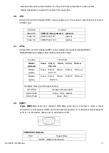
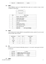
DCD# (Data Carrier Detect)
2
RXD (Received Data)
3
TXD (Transmit Data)
4
DTR (Data Terminal Ready)
5
Ground
6
DSR (Data Set Ready)
7
RTS (Request To Send)
8
CTS (Clear To Send)
9
RI
(
Ring Indicator
)
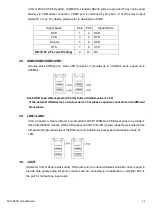
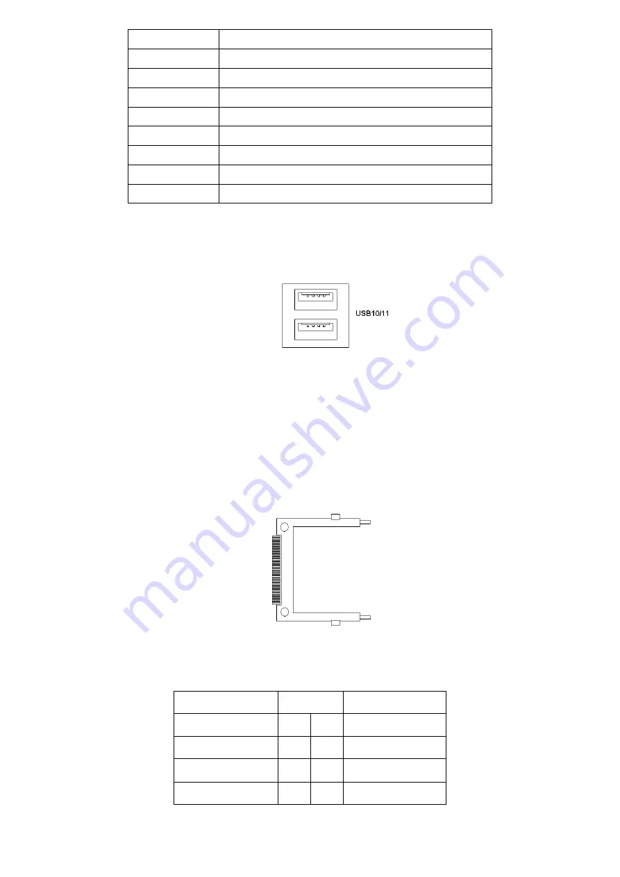
USB10,USB11:
(Double stack USB type A), I/O USB connector, it provides up to 2 USB2.0 ports, speed up to
480Mb/s. USB10 and USB11 connected to ASB-M7101 MIO1 USB0 and USB1.
Each USB Type A Receptacle (2 Ports) Current limited value is 1.5A.
If the external USB device current exceeds 1.5A, please separate connectors into different
Receptacle.
CF:
(
CF Card socket), it is located at TB-522 and serves as an insert interface for Type I and Type II
Compact Flash card. The operating voltage of CF card can be set as 3.3V or 5V.
The default
setting of the product is 5V.
MIO1:
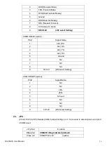
(DF13-40P) TB-522 MIO1 via a dedicated cable connected to ASB-M7101 MIO1.
Signal Name
Pin#
Signal Name
1
2
485+
422_RX-
3
4
485-_422TX-
Ground
5
6
NC
NC
7
8
NC
Summary of Contents for NV-266 C Series
Page 7: ...NV 266XC User Manual 7 Figure 1 1 Dimensions of NV 2663C ...
Page 8: ...NV 266XC User Manual 8 Figure 1 2 Dimensions of NV 2664C ...
Page 9: ...NV 266XC User Manual 9 Figure 1 3 Dimensions of NV 2665C ...
Page 12: ...NV 266XC User Manual 12 Figure 1 9 Rear view of NV 2665C ...
Page 16: ...NV 266XC User Manual 16 2 2 Board Dimensions ...
Page 17: ...NV 266XC User Manual 17 2 3 Jumpers and Connectors Location Board Top ...
Page 18: ...NV 266XC User Manual 18 Board Bottom ...
Page 66: ...NV 266XC User Manual 66 Step 3 Click I agree Step 4 Click Continue Anyway ...
Page 67: ...NV 266XC User Manual 67 Step 5 Click Continue Anyway Step 6 Click Yes to restart the computer ...

