background image

42

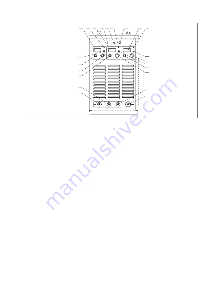
Front panel

Fig. 7-3-1: Front panel

1-3.“Amp/Volt” displayer
When display mode switch indicates to “Amp”:
- LCD displays preset current value, Min. current is 20A;
- LCD displays real welding current during working. 
When display mode switch indicates to “Volt”, LCD displays voltage between output terminals of welding machine.

4-6.Protection indicator
Welding machine will automatically stop working when it is overheat, and the indicator will light up.

7.Default phase indicator
Indicator indicates when power source is default phase.

8.Fan indicator
Indicator indicates whether Fan is on or not.

9.Fan control  
Choose Fan on “ON” or “OFF” position. When choose ON, fan runs, choose off, fan stops running. Keep fan running for 20 
minutes after finishing welding.

10-12.Amp/Volt displayer mode selection switch  

13-15. Start current regulation knob 
It is used to adjust arc starting current under SMAW mode.
Before start arc, work piece is on cold state, increase arc start current so as to improve heat input, which makes the arc start 
easier.

16-18. “Welding current” regulation knob 
It is used to adjust welding current on panel control mode.
Preset proper welding current according to work piece thickness, groove shapes, welding position, wire diameter, etc. 
Welding current decides welding seam depth and wire molten rates.

19-21. Positive output terminal (+)
Connect with electrode holder via welding cable.

22. Negative output terminal (-)
Connect with work piece via ground cable.

I

I

A

A

A

1

2

3

4

5

6

7

8

9

10

A

/

V

A

/

V

1

2

3

4

5

6

7

8

9

10

2

1

3

4

5

6

7

8

9

10

A

/

V

V

V

V

Inverter DCAr c   We  lding Ma c  hine

ARC400

-

3T

START CURR E NT

START C U RRENT

Default p h ase

WELDING CU RRENT

WELDING C U RRENT

START CUR R ENT

WELDING CURR E NT

Protection

Protection

Protection

OFF

ON

FAN CO NTROL

FAN I N DICATOR

1

22

21

20

19

18
11

17

16

15

14

13

12

10

9

8

5

4

2

7

6

3

Summary of Contents for ARC1000

Page 1: ...ly this definitely helps to prolong its enduring quality and reliability things which are both essential prerequisites for getting outstanding results Production specification may change without advance notice The model you purchase is for ARC315 400 500 630 ARC1000 1250 ARC400II ARC400 3T TIG315 400 500 630 TIG1000 1250 TIG400II Please find corresponding models from the Contents Important Please ...

Page 2: ... welding wire are electrically live Incorrectly installed or improperly grounded equipment is a hazard Do not touch live electrical parts of the welding circuit electrodes and wires with your bare skin or wet clothing The operator must wear dry hole free insulating welding gloves and body protection while performs the welding Insulate yourself from work and ground using dry insulating protection w...

Page 3: ... fumes and gases breathing these fumes and gases Welding and cutting sparks can cause fire or explosion touching the work or ground Accidental contact can cause sparks explosion overheating or fire Make sure the area is safe before doing any welding Welding and cutting on closed containers such as tanks drums or containers can cause them to blow up Make sure proper steps have been taken When press...

Page 4: ... gas under high pressure If damaged a Hot parts can burn Ensure equipment is cooled down before perform any work If touching hot parts is needed use proper tools and or wear heavy insulated welding gloves and clothing to prevent burns Do not touch hot parts with bare hand or skin Flying metal or dirt can injure eyes flying metal It can hurt your eyes Remember wear appropriate safety glasses with s...

Page 5: ...hnical data 4 7 Main components list 5 ARC1000 1250 5 1 System components 5 2 Basic equipments for welding 5 3 Interface 5 4 Connections 5 5 Installation and operation 5 6 Technical data 5 7 Main components list 6 ARC400II 6 1 System components 6 2 Basic equipments for welding 6 3 Interface 6 4 Connections 6 5 Installation and operation 6 6 Technical data 6 7 Main components list 7 ARC400 3T 7 1 S...

Page 6: ...mponents list 10 TIG400II 10 1 System components 10 2 Basic equipments for welding 10 3 Interface 10 4 Connections 10 5 Installation and operation 10 6 Technical data 10 7 Main components list 11 REMOTE CONTROLLER 11 1 Wire remote controller support hot plug 11 2 Wireless remote controller 12 TROUBLE SHOOTING 13 CARE AND MAINTENANCE 14 BASIC WELDING TECHNIQUE 14 1 TIG welding technique 14 2 SMAW S...

Page 7: ...ent down slope function when stopping arc and the down slope time is continuous adjustable TIG series only Fig 1 2 1 Schematic diagram 1 3 Output characteristics Please refer to Fig 1 3 1 for output characteristics Fig 1 3 1 Output characteristics 3 1 2 Functional principle This series welding machines apply IGBT soft switch inverter technology 3 phase input volt are rectified by rectifier inverte...

Page 8: ...ehicle manufacture Mechanical industry Maintenance and repair 1 6 Warning label The warning label is affixed onto the top of the power source and it must not be removed or painted over 4 0 15 Overheating Minute OR Reduce Duty Cycle 1 4 Duty cycle Duty cycle is percentage of 10 minutes that a machine can weld at rated load without overheating If overheats thermostat s will open output stops and coo...

Page 9: ...or pipeline industry and suitable to work with generator for field usages ARC400 3T This is multi operator welding machine which integrates 3 units ARC400 machines into one case Three outputs allow three operators to work at the same time or work separately TIG315 400 500 630 The power sources have logical arranged control panel for convenient operation which can perform SMAW simple TIG DC TIG and...

Page 10: ...ctive metallic dust like drillings must not be allowed to get sucked into the machine Note Inadequately dimensioned electrical installations can lead to serious damage The mains lead and its fuse protection must be dimensioned in accordance with the local power supply The technical data shown on the rating plate shall apply 3 2 Machines installation rules According to test the protection degree of...

Page 11: ...d by rolling up coil the cables to two windings in reverse direction and overlap them The number of turns for A is same as the number for B Handle the welding cable and ground cable according to above mentioned method Fig 3 4 1 Welding cables instruction 7 ...

Page 12: ...ower source Ground cable Electrode holder Electrode GOUGING Power source Ground cable Gouging torch Carbon rod Air compressor Ground cable Welding cable Gouging torch Optional Wireless remote contro ller Optional 1 5 6 8 10 7 2 4 9 3 1 10 5 6 8 2 3 4 7 9 A ARC F ORCE DECAY TIME WELDING CUR RENT Wire remote controller Optional PROTECTION PANEL REMOTE A V Inverter DC Arc Welding Machine A R C 4 0 0 ...

Page 13: ...ded distance from the welding areas 5 Amp Volt displayer mode selection switch 6 Welding current regulation knob It is used to adjust welding current on panel control mode Preset proper welding current according to work piece thickness groove shapes welding position wire diameter etc Welding current decides welding seam depth and wire molten rates 7 Remote control socket It is used to connect to t...

Page 14: ...er source Normally the switch flipped to upward means power on To start or stop the welding machine is done by the mains switch in the distribution box Please do not take this circuit breaker as the power switch 2 Input power cable It is 4 pin cable The mixed colored wire must be firmly grounded the rest wires connect to corresponding 3 phase power supply 3 Nameplate 4 Cooling fan Cool down the he...

Page 15: ...lug intype 2 1 3 4 7 8 9 10 2 1 3 4 5 6 7 8 9 10 6 5 Inverter DCArc Welding Machine ARC400 PROTECTION DEFAULT PHASE PANEL REMOTE A V START CURRENT ARC FORCE WELDING CURRENT 1 5 6 8 10 7 2 4 9 3 1 10 5 6 8 2 3 4 7 9 A ARC F ORCE DECAY TIME WELDING CURRENT 1 2 3 4 6 5 7 Remote control socket Socket pin Description 1 2 3 4 5 6 7 Null 9V power supply Remote welding current given signal Power GND Remot...

Page 16: ...he mains Fig 4 5 1 Installation Model Power supply 315 Min power KVA Input protection A Cable size mm 21 45 60 80 6 35 6 Table 4 5 1 Input power supply cable installation single voltage AC220V 3 phase AC220V 10 60Hz Power network Generator Fuse Circuit breaker Input cable Output cable Protective GND wire 38 60 100 120 10 50 10 400 500 28 45 80 100 6 50 6 V A WELDING C URRENT PANEL A V REMOTE PROTE...

Page 17: ...y cable installation multi voltage 3 phase AC220V 380V 440V 10 60Hz Power network Fuse Circuit breaker Input cable Output cable Protective GND wire 38 63 100 6 50 6 28 63 100 6 50 6 400 500 630 Note Welding machine must be taken special design if it is powered by generator please contact with manufacturer if you have such needs The connection between input power supply cable and switch box Fig 4 5...

Page 18: ...ing Gouging Note GOUGING process only is available for the machine which rated current is 500A 1 Switch off the mains switch 2 Plug one end of the ground cable to the output terminal 3 Connect the other end of the ground cable to the work piece 4 Plug the gouging torch cable to output terminal 5 Connect the gas hose to gas outlet of the air compressor or other gas supply tube 6 Switch on the mains...

Page 19: ... MMA 20 315 15 160 0 75 20 400 15 200 0 75 20 500 15 250 0 75 50 630 15 330 0 75 Max open circuit voltage V Protection class Full load efficiency Power factor 80 8 IP21S 89 0 95 2 5 34 2 6 43 2 6 50 2 6 58 576 297 557 636 322 582 686 322 584 Main transformer output reactor H Multi voltage Primary power voltage Frequency Rated output capacity KW Rated input current A Model Protection class Full loa...

Page 20: ...0V 60HZ 745011 00021 380V 50HZ 745011 00022 220 380 440V 60HZ 773002 00003 380V 50HZ 773002 00011 220 380 440V 60HZ 746001 00011 380V 50HZ 746001 00018 220 380 440V 60HZ 263065 00100 380V 50HZ 263065 00311 220 380 440V 60HZ 722001 00070 380V 50HZ 763004 00104 380V 50HZ 763004 00103 220 380 440V 60HZ 740016 00017 380V 50HZ 720041 00008 380V 50HZ 740002 00046 380V 50HZ 220 380 440V 60HZ 220 380 440V...

Page 21: ...20455 00002 380V 50HZ 220455 00004 220 380 440V 60HZ 220281 00008 380V 50HZ 220281 00005 220 380 440V 60HZ 264011 00121 380V 50HZ 264011 00144 220 380 440V 60HZ 220 380 440V 60HZ 220 380 440V 60HZ 220 380 440V 60HZ Main control board Drive board No Item Stock No 13 14 15 Power transformer Main transformer Resonant inductor Polypropylene capacitor Current transformer 16 17 18 19 20 Polypropylene ca...

Page 22: ...V 50Hz CE mode 210580 00633 220 380 440V 60HZ 210310 00020 380V 50HZ 415V 50Hz CE mode 210310 00088 220 380 440V 60HZ 763001 00043 380V 50HZ 763001 00060 415V 50Hz 763001 00052 CE model 763001 00174 763001 00195 220 380 440V 60HZ 220629 00023 380V 50HZ 415V 50Hz CE mode 220629 00148 220 380 440V 60HZ 220521 00007 380V 50HZ 415V 50Hz CE mode 220521 00040 220 380 440V 60HZ 722001 00073 380V 50HZ 415...

Page 23: ...nge inductor Output diode radiator Table 4 7 2 Components list for ARC400 1 6 7 8 9 10 11 12 3 4 5 2 19 No Item Stock No 262005 00248 380V 50HZ 262005 00795 220 380 440V 60HZ 740002 00037 740002 00038 380V 50HZ 740002 00026 262011 00131 380V 50HZ 262011 00490 220 380 440V 60HZ 745011 00022 380V 50HZ 745011 00022 220 380 440V 60HZ 740016 00009 380V 50HZ 773002 00011 220 380 440V 60HZ 746001 00017 3...

Page 24: ...0V 60HZ 745008 00006 380V 50HZ 735006 00029 380V 50HZ 735006 00019 220 380 440V 60HZ 220455 00002 380V 50HZ 220455 00004 220 380 440V 60HZ 220281 00008 380V 50HZ 220281 00005 220 380 440V 60HZ 264011 00025 380V 50HZ 264011 00144 220 380 440V 60HZ 415V 50Hz 415V 50Hz 220 380 440V 60HZ 415V 50Hz 415V 50Hz 415V 50Hz 415V 50Hz 415V 50Hz 415V 50Hz 415V 50Hz 415V 50Hz 415V 50Hz 415V 50Hz 220 380 440V 60...

Page 25: ...00204 CE 263065 00399 220 380 440V 60HZ 722001 00070 380V 50HZ 763004 00010 380V 50HZ 763004 00116 CE 763004 00010 220 380 440V 60HZ 740016 00017 380V 50HZ 740016 00017 220 380 440V 60HZ 720041 00010 263071 00130 380V 50HZ 263071 00281 CE 263071 00382 220 380 440V 60HZ 210580 00198 380V 50HZ 210580 00673 220 380 440V 60HZ 210310 00032 380V 50HZ 210310 00095 220 380 440V 60HZ 763001 00043 380V 50HZ...

Page 26: ...008 00008 380V 50HZ 415V 50Hz CE model 220 380 440V 60HZ 735006 00029 380V 50HZ 415V 50Hz CE model 735006 00029 220 380 440V 60HZ 220455 00002 380V 50HZ 415V 50Hz CE model 220455 00004 220 380 440V 60HZ 220281 00012 380V 50HZ 415V 50Hz CE model 220281 00031 220 380 440V 60HZ 264011 00027 380V 50HZ 415V 50Hz CE model 264011 00027 220 380 440V 60HZ Table 4 7 4 Components list for ARC630 Note This ta...

Page 27: ...g when it is overheat and the indicator will light up 2 Fault indicator Welding machine will automatically stop working when it is in fault and the indicator will light up 3 Default phase indicator Indicator indicates when power source is default phase 4 Amp Volt displayer When display mode switch indicates to Amp LCD displays preset current value Min current is 20A LCD displays real welding curre...

Page 28: ...ust arc starting current under SMAW mode Before start arc work piece is on cold state increase arc start current so as to improve heat input which makes the arc start easier 10 Welding current regulation knob It is used to adjust welding current on panel control mode Preset proper welding current according to work piece thickness groove shapes welding position wire diameter etc Welding current dec...

Page 29: ...thing bolt To ensure operators not being harmed and welding machine working normally make sure the earthing bolt is grounded firmly by protective GND wire or make sure the wire mixed colored of the power supply cable is grounded firmly protective GND 5 4 Connections Output socket The output socket of this power source has two types one is fast plug in type another one is compression type Make sure...

Page 30: ...wer supply cable installation single voltage AC380V 400V 415V 440V The connection between input power supply cable and switch box Fig 5 5 2 Warning Never connection when equipment is power on The connection must be carried out by a qualified electrician Do not connect two units of power sources to the same one circuit breaker Connected to the correct input voltage circuit breaker input cable as pe...

Page 31: ...itch on Amp position 6 Adjust arc length L S M switch according to welding cable length 7 Select SMAW by the SMAW Gouging switch on front panel 8 Adjust arc start current arc force current welding current according to electrode diameter welding position 9 Welding Gouging 1 Switch off the mains switch 2 Use short circuit copper block to connect two positive output terminals then connect gouging tor...

Page 32: ...e 5 6 1 Single voltage Primary power voltage Frequency Rated output capacity KW Rated input current A Rated duty cycle Range of output current A Model Welding electrode diameter mm Weight Kg Dimension mm 3 phase AC380V 400V 415V 440V 10 50 60Hz 1000 1250 44 83 79 76 71 100 60 1000 140 700 0 75 82 4 Arc force current A Arc starting current A MMA Max open circuit voltage V Protection class Full load...

Page 33: ...0HZ 380V 60HZ 415V 50HZ 740002 00052 740002 00053 380V 50HZ 262011 00113 380V 50HZ 745011 00001 380V 50HZ 740016 00009 380V 50HZ 746001 00017 380V 50HZ 746001 00018 380V 60HZ 746001 00019 415V 50HZ 263071 00274 380V 50HZ 763001 00041 380V 50HZ 763001 00109 415V 50HZ 210580 00653 380V 50HZ 210310 00032 380V 50HZ 263071 00275 380V 50HZ 380V 50HZ 380V 60HZ 415V 50HZ 380V 60HZ 415V 50HZ 380V 60HZ 415V...

Page 34: ... 1 No Item Stock No Front plate 2 Assembly cable socket type Rear panel Circuit breaker Junction box Fan Middle board Power transformer Main control board Drive board Second layer board Resonant inductor Resonant capacitor Capacitor filter inductor Polypropylene capacitor Current sensor Output reactor Base plate 3 4 5 6 7 8 9 10 11 12 13 14 15 16 17 18 262005 00208 380V 50HZ 740002 00052 740002 00...

Page 35: ... 00011 380V 50HZ 264011 00020 380V 50HZ 735006 00029 380V 50HZ 220455 00002 380V 50HZ 745008 00006 380V 50HZ 220281 00008 380V 50HZ 264005 00039 264005 00036 380V 50HZ 735007 00038 380V 50HZ 220005 00008 380V 50HZ 722001 00067 380V 50HZ 735005 00003 380V 50HZ 722001 00070 380V 50HZ 720021 00017 380V 50HZ 220149 00007 380V 50HZ 380V 50HZ Table 5 7 2 Components list for ARC1250 Note This table is fo...

Page 36: ...at are not described in this operating manual Also certain illustrations may be very slightly different from the actual controls on your machine However these controls function in exactly the same way Ground cable Welding cable 1 5 6 8 10 7 2 4 9 3 1 10 5 6 8 2 3 4 7 9 A ARC FORCE DECAY TIM E WELDING C URRENT Wire remote controller Optional Power s ource 7 8 9 10 PROT ECTION WELDING CURRENT ST ART...

Page 37: ...trol cable then user can adjust welding current arc force current on Remote control mode It is convenient to realize welding control in extended distance 7 Start current regulation knob It is used to adjust arc starting current under SMAW mode Before start arc work piece is on cold state increase arc start current so as to improve heat input which makes the arc start easier 8 Arc force current reg...

Page 38: ...tive GND wire or make sure the protective GND wire mixed colored of the input power cable is grounded firmly 6 4 Connections Please refer to ARC315 400 500 630 the relevant 4 4 Connections in details 6 5 Installation and operation Warning Electric shock is very dangerous If the machine is plugged into the mains electricity supply during installation there is a high risk of very serious injury and ...

Page 39: ...stallation single voltage AC220V Model Power supply 3 phase AC380V 400V 415V 440V 525V 10 50 60Hz 28 45 50 63 4 50 4 400II Min capacity KVA Power network Generator Fuse Circuit breaker Input cable Output cable Protective GND wire Min cable size mm 2 Input protection A Table 6 5 2 Input power supply cable installation single voltage AC380V 400V 415V 440V 525V A V 4 3 2 1 5 6 7 8 9 10 4 3 2 1 5 6 7 ...

Page 40: ...r supply cable and switch box Fig 6 5 2 Warning Never connection when equipment is power on The connection must be carried out by a qualified electrician Do not connect two units of power sources to the same circuit breaker Connected to the correct input voltage circuit breaker input cable as per the specification on Table 6 5 1 Table 6 5 3 Fig 6 5 2 Connection between input power supply cable and...

Page 41: ...id electrode E6013 1 Connect electrode holder with output terminal connect work piece with output terminal 2 Place switch on ON position power on 3 Choose Panel control mode on control panel 4 Choose Amp Volt switch on Amp position 5 Adjust arc start current arc force current welding current according to electrode diameter welding position 6 Adjust L S M switch on control panel according to weldin...

Page 42: ...orce current A Arc starting current A MMA Protection class Full load efficiency Power factor full load Welding electrode diameter mm Weight Kg Dimension mm3 11 3 20 400 15 200 0 75 IP21S 89 0 95 2 6 Main transformer output reactor Insulation class 50 576 297 557 H Table 6 6 2 ARC400II technical data multi voltage 6 7 Main components list 31 30 29 28 16 15 14 12 13 4 5 1 2 6 3 9 8 7 10 11 17 18 19 ...

Page 43: ...2 00011 220 60HZ 746001 00011 380V 50HZ 746001 00010 220 60HZ 263065 00097 380V 50HZ 263065 00006 220 60HZ 722001 00070 380V 50HZ 763004 00041 380V 50HZ 740016 00017 380V 50HZ 720041 00008 380V 50HZ 263071 00115 380V 50HZ 263071 00023 220 60HZ 210580 00441 380V 50HZ 210310 00020 380V 50HZ 763001 00043 380V 50HZ 763001 00050 220 60HZ 220629 00020 380V 50HZ 220629 00150 220 60HZ 220521 00007 380V 50...

Page 44: ...00018 220 60HZ 220455 00002 380V 50HZ 220281 00008 380V 50HZ 220281 00008 220 60HZ 264011 00121 380V 50HZ 264011 00121 220 60HZ V 220V60HZ V V Table 6 7 1 Components list for ARC400II Note This table is for reference only and the detail of actual product shall prevail If no special remarks the input voltage mentioned in above table is three phase 40 ...

Page 45: ...e parameters that are not described in this operating manual Also certain illustrations may be very slightly different from the actual controls on your machine However these controls function in exactly the same way Power source Ground cable Welding cable Welding cable Welding cable Ⅱ I Ⅱ Ⅲ I Ⅲ A A A 1 2 3 4 5 6 7 8 9 10 A V A V 1 2 3 4 5 6 7 8 9 10 2 1 3 4 5 6 7 8 9 10 A V V V V Inverter DCArcWel...

Page 46: ...ent regulation knob It is used to adjust arc starting current under SMAW mode Before start arc work piece is on cold state increase arc start current so as to improve heat input which makes the arc start easier 16 18 Welding current regulation knob It is used to adjust welding current on panel control mode Preset proper welding current according to work piece thickness groove shapes welding positi...

Page 47: ...ool down the heat components in the welding machine 26 Earthing bolt To ensure operators not being harmed and welding machine working normally make sure the earthing bolt is grounded firmly by protective GND wire or make sure the protective GND wire mixed colored of the input power cable is grounded firmly 27 Input cable cleat 28 Nameplate 7 4 Connections Output socket The output socket of this po...

Page 48: ...e OFF position the machine is unplugged from the mains Fig 7 5 1 Installation Model Power supply Min power capacity KVA 400 3T 3 phase AC220V 10 50 60Hz 84 150 200 3X18 35 95 18 Fuse Circuit breaker Input cable Min cable size mm 2 Input protection A Output cable Protective GND wire Table 7 5 1 Input power supply cable installation single voltage 220V Ⅱ I Ⅲ A A A 1 2 3 4 5 6 7 8 9 10 A V A V 1 2 3 ...

Page 49: ...hen equipment is power on The connection must be carried out by a qualified electrician Do not connect two units of power sources to the same circuit breaker Connected to the correct input voltage circuit breaker input cable as per the specification on Table 7 5 1 Table 7 5 2 Fig 7 5 2 Connection between input power supply cable and switch box L1 L2 L3 GND A7 A6 A5 A4 A2 L1 L2 L3 Yellow Green prot...

Page 50: ...ding current according to electrode diameter welding position 6 Welding Note This is multi operator welding machine which integrates 3 units ARC400 machines into one case Three outputs allow three operators to work at the same time or work separately 7 6 Technical data Note Please use the machine under the allowed power supply voltage range marked in the nameplate The technical data with the basic...

Page 51: ...hunt Base plate Main transformer II Main transformer III Main transformer I 262005 00228 380V 50Hz 740004 00052 740004 00057 380V 50Hz 262011 00124 380V 50Hz 745011 00021 380V 50Hz 740016 00009 380V 50Hz 746001 00017 380V 50Hz 763001 00041 380V 50Hz 210580 00138 380V 50Hz 210310 00032 380V 50Hz 220149 00048 220149 00049 380V 50Hz 263071 00014 380V 50Hz 220521 00026 220521 00027 220521 00028 380V 5...

Page 52: ... 27 28 29 30 31 32 33 722001 00070 380V 50Hz 264005 00046 380V 50Hz 264011 00047 380V 50Hz 264005 00048 380V 50Hz 735007 00089 380V 50Hz 220005 00040 380V 50Hz 722001 00067 380V 50Hz 720021 00017 380V 50Hz 735005 00002 380V 50Hz 264011 00048 380V 50Hz 264011 00048 380V 50Hz 220455 00002 380V 50Hz 735006 00029 380V 50Hz 745008 00006 380V 50Hz Table 7 7 1 Components list for ARC400 3T Note This tabl...

Page 53: ...er to supply the machine with shielding gas Welding wire GOUGING Power source Ground cable Gouging torch Carbon rod Air compressor welding Gouging torch Optional 1 5 6 8 10 7 2 4 9 3 1 10 5 6 8 2 3 4 7 9 A ARCFOR CE DEC AYTIME WELDING C URRENT Wire rmote controller Optional Power source Ground cable Welding cable TIG torch A V 4 STEP 2 STEP REMOTE PANEL V A Inverter MMA TIG Arc Welding Machine TIG...

Page 54: ...ed to SMAW the machine is to work on SMAW When it is on TIG the machine is to work on TIG 6 4 step 2 step switch used in TIG welding Press this button to switch between 2 step and 4 step operation mode the indicator will lights up accordingly 8 3 Interface Note You may find that your machine has certain functions or some parameters that are not described in this operating manual Also certain illus...

Page 55: ...torch trigger to start welding Open solenoid valve shielding gas will flow out to expel air from torch hose pre gas time depends on the hose length Then HF ignition device works and starts arc Output current starts at initial current to welding current and time of initial current output depends on the time that torch trigger is pressed and held b Release torch trigger Start normal welding c Press ...

Page 56: ...nt Prolong this time can decrease heat on crater filler mode reduce the temperature of welding seam tail reduce gas hole or sinkhole problems caused by temperature drop and decrease crater filler hole 10 Start current regulation knob It is used to adjust arc starting current under SMAW mode Before start arc work piece is on cold state increase arc start current so as to improve heat input which ma...

Page 57: ...nding 3 phase power supply 3 Earthing bolt To ensure operators not being harmed and welding machine working normally make sure the earthing bolt is grounded firmly by protective GND wire or make sure the protective GND wire mixed colored of the input power cable is grounded firmly 4 Nameplate 5 Cooling fan Cool down the heat components in the welding machine 6 Gas inlet Connect to Argon gas regula...

Page 58: ...DING CURRENT 1 2 3 4 6 5 7 Remote control socket Socket pin 1 2 3 4 5 6 7 Fast plug in type Compression type 8 5 Installation and operation Description Torch trigger TIG mode 9V power supply Remote welding current given signal Power GND Remote arc force current given signal Remote controller digital signal Table 8 4 1 Connections Warning Electric shock is very dangerous If the machine is plugged i...

Page 59: ...tor onto the gas cylinder and tighten it connect gas hose with shielding gas regulator and gas inlet on welding machine rear panel 2 Connect torch with output terminal connect work piece with output terminal 3 Place switch on ON position power on 4 Choose SMAW TIG switch on TIG position 5 Choose Panel control mode on control panel 6 Choose Amp Volt switch on Amp position 7 Adjust welding current a...

Page 60: ...ess is only available for the machine which rated current is 500A 8 6 Technical data Please refer to ARC315 400 500 630 the relevant 4 6 Technical data in details 8 7 Main components list TIG315 400 500 630 1 Switch off the mains switch 2 Plug one end of the ground cable to the output terminal 3 Connect the other end of the ground cable to the work piece 4 Plug the gouging torch cable to output te...

Page 61: ...18 220 380 440V 60HZ 746001 00034 CE model 752001 00014 380V 50HZ 752001 00014 220 380 440V 60HZ 752001 00014 CE model 263065 00100 380V 50HZ 263065 00311 220 380 440V 60HZ 722001 00070 380V 50HZ 763004 00041 380V 50HZ 763004 00103 220 380 440V 60HZ 740016 00017 380V 50HZ 720041 00008 380V 50HZ 220431 00005 380V 50HZ 220431 00032 220 380 440V 60HZ 220263 00005 380V 50HZ 220263 00016 220 380 440V 6...

Page 62: ...0067 380V 50HZ 264011 00121 380V 50HZ 264011 00144 220 380 440V 60HZ 220281 00008 380V 50HZ 220281 00005 220 380 440V 60HZ 220455 00002 380V 50HZ 220455 00004 220 380 440V 60HZ 735006 00027 380V 50HZ 735006 00019 220 380 440V 60HZ 415V 50HZ CE model 415V 50HZ CE model 415V 50HZ CE model 415V 50HZ CE model 220 380 440V 60HZ 415V 50HZ CE model 415V 50HZ CE model 415V 50HZ CE model 220 380 440V 60HZ ...

Page 63: ...V 50HZ 720021 00017 380V 50HZ 720021 00021 415V 50HZ 745008 00006 380V 50HZ 220005 00007 380V 50HZ 735007 00048 380V 50HZ 722001 00067 380V 50HZ 264011 00025 380V 50HZ 220281 00008 380V 50HZ 220455 00002 380V 50HZ 735006 00029 380V 50HZ Table 8 7 2 Components list for TIG500 Front plate Rear panel Circuit breaker Juction box Solenoid valve Base plate Polypropylene capacitor Output reactor Shunt No...

Page 64: ...3001 00060 415V 50HZ 220629 00016 380V 50HZ 220521 00029 380V 50HZ 722001 00075 380V 50HZ 220047 00006 380V 50HZ 220149 00007 380V 50HZ 264005 00088 380V 50HZ 735005 00003 380V 50HZ 720021 00017 380V 50HZ 720021 00021 415V 50HZ 745008 00008 380V 50HZ 220005 00008 380V 50HZ 735007 00073 380V 50HZ 722001 00067 380V 50HZ 264011 00027 380V 50HZ 220281 00012 380V 50HZ 220455 00002 380V 50HZ 735006 0002...

Page 65: ...in fault and the indicator will light up 3 Default phase indicator Indicator indicates when power source is default phase 4 Amp Volt displayer When display mode switch indicates to Amp LCD displays preset current value Min current is 20A When display mode switch indicates to Volt LCD displays voltage between output terminals of welding machine 5 Down slope time adjustment knob TIG mode down slope ...

Page 66: ...hen arc voltage is low increase current to shorten the droplet transfer time 11 Welding current regulation knob It is used to adjust welding current on panel control mode Preset proper welding current according to work piece thickness groove shapes welding position wire diameter etc Welding current decides welding seam depth and wire molten rates 12 Positive output terminal It is used to connect w...

Page 67: ...ing bolt is grounded firmly by protective GND wire or make sure the protective GND wire mixed colored of the input power cable is grounded firmly 4 Nameplate 5 Cooling fan Cool down the heat components in the welding machine 6 Gas inlet Connect to Argon gas regulator with gas hose 9 4 Connections Output socket The output socket of this power source has two types one is fast plug in type another on...

Page 68: ...witch according to welding cable length 7 Choose SMAW TIG switch on SMAW position 8 Adjust arc start current arc force current welding current according to wire diameter welding position 9 Welding HF TIG welding 1 Screw shielding gas regulator onto the gas cylinder and tighten it connect gas hose with shielding gas regulator and gas inlet on welding machine rear panel 2 Use short circuit copper bl...

Page 69: ...k to connect two negative output terminals connect ground cable with short circuit copper block then connect the other end of the ground cable to the work piece 4 Connect the gas hose to gas outlet of the air compressor or other gas supply tube 5 Switch on the mains switch 6 Select Gouging by the SMAW TIG Gouging switch on front panel 7 Set the required current value by rotating welding current kn...

Page 70: ...01 00109 415V 50HZ 210580 00653 380V 50HZ 210310 00032 380V 50HZ 220263 00005 380V 50HZ 220149 00010 380V 50HZ 722001 00062 380V 50HZ 220155 00001 380V 50HZ 722001 00074 380V 50HZ 220521 00002 380V 50HZ 753001 00020 380V 50HZ 763004 00037 380V 50HZ 220431 00018 380V 50HZ 740016 00017 380V 50HZ 220047 00006 380V 50HZ 220629 00009 380V 50HZ 264011 00019 380V 50HZ 735006 00029 380V 50HZ 220455 00002 ...

Page 71: ... 00019 415V 50HZ 752001 00014 380V 50HZ 763001 00041 380V 50HZ 763001 00109 415V 50HZ 210580 00653 380V 50HZ 210310 00032 380V 50HZ 220263 00005 380V 50HZ 220149 00010 380V 50HZ 722001 00062 380V 50HZ 220155 00001 380V 50HZ 722001 00074 380V 50HZ 220521 00002 380V 50HZ 753001 00020 380V 50HZ 763004 00037 380V 50HZ 220431 00018 380V 50HZ 740016 00017 380V 50HZ 220047 00006 380V 50HZ 220629 00009 38...

Page 72: ...gas hose gas cylinder to supply the machine with shielding gas Welding wire Ground cable Welding cable TIG torch Wireless remote controller Optional ARC FORCE WELDING C URRENT WIRELESS RE MOTE CONTROLLER 1 5 6 8 10 7 2 4 9 3 1 10 5 6 8 2 3 4 7 9 A ARC FORCE DECAY TIME WELDING C URRENT Wire remote controller Optional Power source 4 3 2 1 5 6 7 8 9 10 4 ST EP 2 STEP TIG SM AW A V 4 3 2 1 5 6 7 8 9 1...

Page 73: ...ontrol switch When it is on Panel control you can adjust welding current arc force current or down slope time through the knobs and switches on the panel when it is on Remote control you can adjust the above parameters through remote controller in an extended distance from the welding areas 8 Welding current regulation knob It is used to adjust welding current on panel control mode Preset proper w...

Page 74: ... It is used to connect to the wire remote controller with remote control cable to adjust welding current arc force current or down slope time when it is on the Remote control mode used to weld in extended distance To weld in normal distance on TIG it is used to connect TIG torch s control cable directly 14 Negative output terminal It is connected to work piece via ground cable on SMAW mode and con...

Page 75: ...ning Warning Electric shock is very dangerous As soon as the power source is switch on the welding electrode is power on Make sure that the electrode does not touch any person or conductor or grounded parts e g lifting appliance etc SMAW welding with basic electrode E7016 E7018 1 Connect electrode holder with output terminal connect work piece with output terminal 2 Place switch on ON position pow...

Page 76: ... switch on ON position power on 4 Choose SMAW TIG switch on TIG position 5 Choose Panel control mode on control panel 6 Choose Amp Volt switch on Amp position 7 Select 2 step 4 step 8 Adjust welding current according to plate thickness 9 Adjust down slope time according to welding current value 10 Open gas valve of shielding gas regulator press torch trigger adjust flow rate release torch trigger ...

Page 77: ... IGBT module No Item Stock No 1 3 4 5 6 7 8 9 10 11 12 13 14 15 16 17 18 19 20 21 22 23 24 25 2 Output quick socket 262005 00212 380V 50HZ 740002 00048 740002 00046 380V 50HZ 262011 00117 380V 50HZ 745011 00021 380V 50HZ 773002 00029 380V 50HZ 746001 00011 380V 50HZ 752001 00014 380V 50HZ 263065 00097 380V 50HZ 722001 00070 380V 50HZ 220263 00005 380V 50HZ 763004 00041 380V 50HZ 740016 00017 380V ...

Page 78: ... 34 35 735005 00002 380V 50HZ 720021 00021 380V 50HZ 220005 00022 380V 50HZ 264005 00028 380V 50HZ 745008 00006 380V 50HZ 220479 00011 380V 50HZ 735006 00029 380V 50HZ 220455 00002 380V 50HZ 220281 00008 380V 50HZ 264011 00121 380V 50HZ Table 10 7 1 Components list for TIG400II Note This table is for reference only and the detail of actual product shall prevail If no special remarks the input volt...

Page 79: ...ding machine knob 4 Socket connect to remote control cable 5 Socket connect to torch trigger cable TIG welding ONLY Fig 11 1 2 Remote controller connection Operating guide 1 Connect welding machine control socket and remote controller socket 4 Fig 11 1 1 via 7 pin control cable 2 Connect remote controller socket 5 Fig 11 1 1 with torch trigger cable TIG welding ONLY 3 Place welding machine circuit...

Page 80: ...n prevent falling and is convenient for operating Long distance control is up to 100m operator can adjust the welding current and arc force current remotely Two methods to adjust fast adjustment slow adjustment Compact design can be effective anti raining light weight easy to carry Parameter adjustment button Fig 11 2 1 Wireless remote controller 1 Current digital displayer Indicate welding curren...

Page 81: ...r 4 The digital displayer shows the current value adjust the welding current and arc force current in accordance with the welding requirements 5 Remove the clamp from the electrode holder or remove remote controller from work piece when complete the regulation and be ready for welding Important Ensure the remote controller is grounded well and the clamp connect with electrode holder tightly Avoid ...

Page 82: ...le the machine is working normally 1 The following components may be damaged IGBT module 3 phase rectify module output diode module or other components 2 Drive board is damaged 3 Short circuit of the cable 1 Check and replace 2 When IGBT Module is damaged please check 12Ω 5 1Ω resistance or SR160 on drive board is damaged or not 3 Check and repair 03 Welding current is unstable 1 Phase missing 2 T...

Page 83: ... check at regular intervals see Safety rules Dismantle machine side panels and clean machine inside with clean and low pressurecompressed air by professional technician not less than twice per year Clean the components at a certain distance only If a lot of dust has accumulated clean the cooling air ducts Maintenance of water cooled welding torch For water cooled welding torch Check the connection...

Page 84: ... very pure and concentrated arc which provides the controlled melting of most metals into a weld pool TIG welding offers the user the greatest amount of flexibility to weld the widest range of material and thickness and types DC TIG welding is also the cleanest weld with no sparks or spatter Fig 14 1 2 TIG arc Low Current High Current Fig 14 1 3 Low current Fig 14 1 4 High current The intensity of...

Page 85: ...h Filler Wire Technique Fig 14 1 13 Add TIG filler wire It is necessary in many situations with TIG welding to add a filler wire into the weld pool to build up weld reinforcement and create a strong weld Once the arc is started the torch tungsten is held in place until a weld pool is created a circular movement of the tungsten will assist is creating a weld pool of the desired size Once the weld p...

Page 86: ...lways ensure to grind the tungsten in a longitudinal direction on the grinding wheel Tungsten electrodes are manufactured with the molecular structure of the grain running lengthwise and thus grinding crosswise is grinding against the grain If electrodes are ground crosswise the electrons have to jump across the grinding marks and the arc can start before the tip and wander Grinding longitudinally...

Page 87: ... the metal alloy and the intended use of the electrode The Metal Wire Core works as conductor of the current that maintains the arc The core wire melts and is deposited into the welding pool The covering on a shielded metal arc welding electrode is called Flux The flux on the electrode performs many different functions These include producing a protective gas around the weld area providing fluxing...

Page 88: ...o long reduces penetration produces spatter and gives a rough surface finish to the weld An excessively short arc will cause sticking of the electrode and result in poor quality welds General rule of thumb for down hand welding is to have an arc length no greater than the diameter of the core wire Electrode Angle The angle that the electrode makes with the work is important to ensure a smooth even...

Page 89: ...is proportional to carbon rod diameter Generally consult the follow formula to choose current I 30 50 D I Welding current A D Carbon rod diameter mm For a certain diameter carbon rod if current is small then arc is not stable and carbon inclusion defect occurs easily increase current appropriately can improve gouging speed smooth surface of dadoing increase its width In practice choose larger curr...

Page 90: ...high can improve gouging speed and dadoing surface smooth degree if pressure is low easy to cause slag inclusion on dadoing surface Usually pressure is 0 4 0 6Mpa Moisture content and oil content in compressed air can be taken by filter unit installed in compressed air pipeline Extension length of carbon rod Extension length is carbon length from tip to end of carbon rod In manual CAC A extension ...

Reviews: