-BL296*B16F*4A20 6/11-
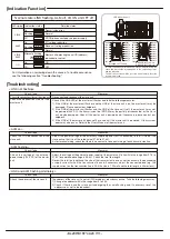
[Connection]
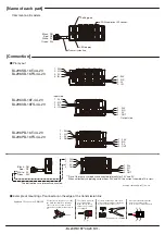
[Name of each part]
■
Pin layout
Input side
1
:
24V
2
:
N.C
3
:
0V
4
:
OUT
BL296SB-16F-4A-20
BL296SB-16FS-4A-20
BL296XB-16F-4A-20
BL296XB-16FS-4A-20
Common to all models
BL296PB-16F-4A-20
BL296PB-16FS-4A-20
Black : DN
Red : DP
White : 0V
Green : 24V
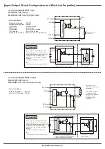
*The dotted lines are internally connected.
**Pins of the same symbols are connected internally for 24V and 0V.
When collectively supplying current from 24V and 0V, the current should be 1A or less.
■
Example of mounting LP connector on the edge of the transmission line
Applicable LP connector: LP-WW-10P
4 3
2 1
A
B
C
Cover
Pressure weld using a dedicated
tool so that the fittings of the body
are in the holes of the cover.
After pressure welding, make
sure to check that hooks
③
to
⑥
are securely engaged.
The state in which the
cover is mounted
Make sure to check
that hooks
①
and
②
are engaged.
① ②
⑤ ⑥
③ ④
Dedicated tool: LP-TOOL
Output side
1
:
24V
2
:
N.C
3
:
0V
4
:
IN
1
:
24V
2
:
N.C
3
:
0V
4
:
IN
1
:
24V
2
:
N.C
3
:
0V
4
:
IN
1
:
24V
2
:
N.C
3
:
0V
4
:
OUT
1
:
24V
2
:
N.C
3
:
0V
4
:
OUT
1
:
24V
2
:
N.C
3
:
0V
4
:
OUT
1
:
24V
2
:
N.C
3
:
0V
4
:
OUT
e-CON-compliant 4P socket
Black : DN
Red : DP
White : 0V
Green : 24V
Example of BL296PB-16F
□
-4A-20
LED display
Setting port
Transmission line
Put the lines in the grooves so that
the black line (DN) is on the hinge
side of the cover, fold A to the B
side and hook them with hook C to
fix.


