-BL296*B16F*4A20 7/11-
[Indication Function]
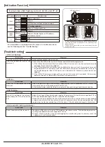
LED indication unit
IN 0
IN 1
LINK
ALM
IN 2
IN 3
IN 4
IN 5
IN 6
IN 7
OUT 0
OUT 1
OUT 2
OUT 3
OUT 4
OUT 5
OUT 6
OUT 7
I/O 0
I/O 1
LINK
ALM
I/O 2
I/O 3
I/O 4
I/O 5
I/O 6
I/O 7
I/O 8
I/O 9
I/O 10
I/O 11
I/O 12
I/O 13
I/O 14
I/O 15
BL296XB-16F
□
-4A-20
BL296SB-16F
□
-4A-20
BL296PB-16F
□
-4A-20
Indication status
Detailed states
Normal
I/O voltage reduction
Slave unit voltage reduction
Transmission error
DP/DN disconnected or no power supply
Normal
Master unit detecting the unit ID (address)
redundant or not set
ON
OFF
Flashing
On
Flashing
Alternate flashing
On
Off
Off
On
Off
LINK
ALM
For information on narrowing down the cause of a trouble occurrence,
see the following section “Troubleshooting.”
Normal state: LINK flashing, ALM off, I/O ON on/OFF off
LINK
LINK
ALM
I/O
LED symbol
ALM
[Troubleshooting]
<LINK not flashing>
<ALM on>
<ALM flashing>
<LINK and ALM flashing alternately>
Check items
Measures
Check items
Measures
Check items
Measures
Check items
Measures
Check the connection status of the slave unit. Disconnect and reconnect the slave unit.
Check if the LINK LED of the master unit flashes and take the following measures.
1) If the LINK of the master unit flashes and the LINK of the slave unit is on, the master unit may be
damaged. Please contact our helpdesk.
2) If the LINK of the master unit flashes and the LINK of the slave unit is off, the master unit may not
be powered (24V DC), the transmission line (DP/DN) may be partially disconnected, or the slave
unit may be damaged. Check if the master unit is powered and, if necessary, please contact our
helpdesk.
3) If the LINK of the master unit does not flash, check if the master unit is powered. Other system
errors may also occur. Refer to the User’s Manual of the master unit.
Adjust the power voltage of the externally supplied power that is connected to the I/O side of the
slave unit so that it is at the rated value (21.6V to 27.6V).
As for terminal wiring, check that there is no contact or incorrect wiring of each transmission line.
Adjust the voltage of the external power supply of the master unit to lie within the range from 21.6 to
27.6V (recommended voltage is 26.4V). Check the total line length.
Review the total line length and the size of the transmission line so as not to connect a load exceeding
a supply current limit on the transmission line and, if necessary, adjust the connected load (e.g. the
supply current on the transmission line is 2A if the size is 1.25mm
2
and the total length is 50m or less).
The address of the slave unit is not set (255) or address redundancy occurs. Take the following measures.
1) Change the address within the range from 0 to 254.
2) Check if there is another slave unit undergoing the same flashing and, if necessary, reset the
address so as not to be redundant.
Check the I/O side connection of the
slave unit.
Check the voltage of the external
power supply (24V DC) of the master
unit.
Check the address of the slave unit.
Check the connection status of the
master unit.
In case of an abnormal indication status, narrow down the
cause and remove the trouble based on the on/flashing status
and the left table.
The indication status will be restored automatically after the
trouble is removed.


