Antaira Technologies - Industrial Media Converter
IMP-C1000-SFP-bt Series User Manual V1.0
5
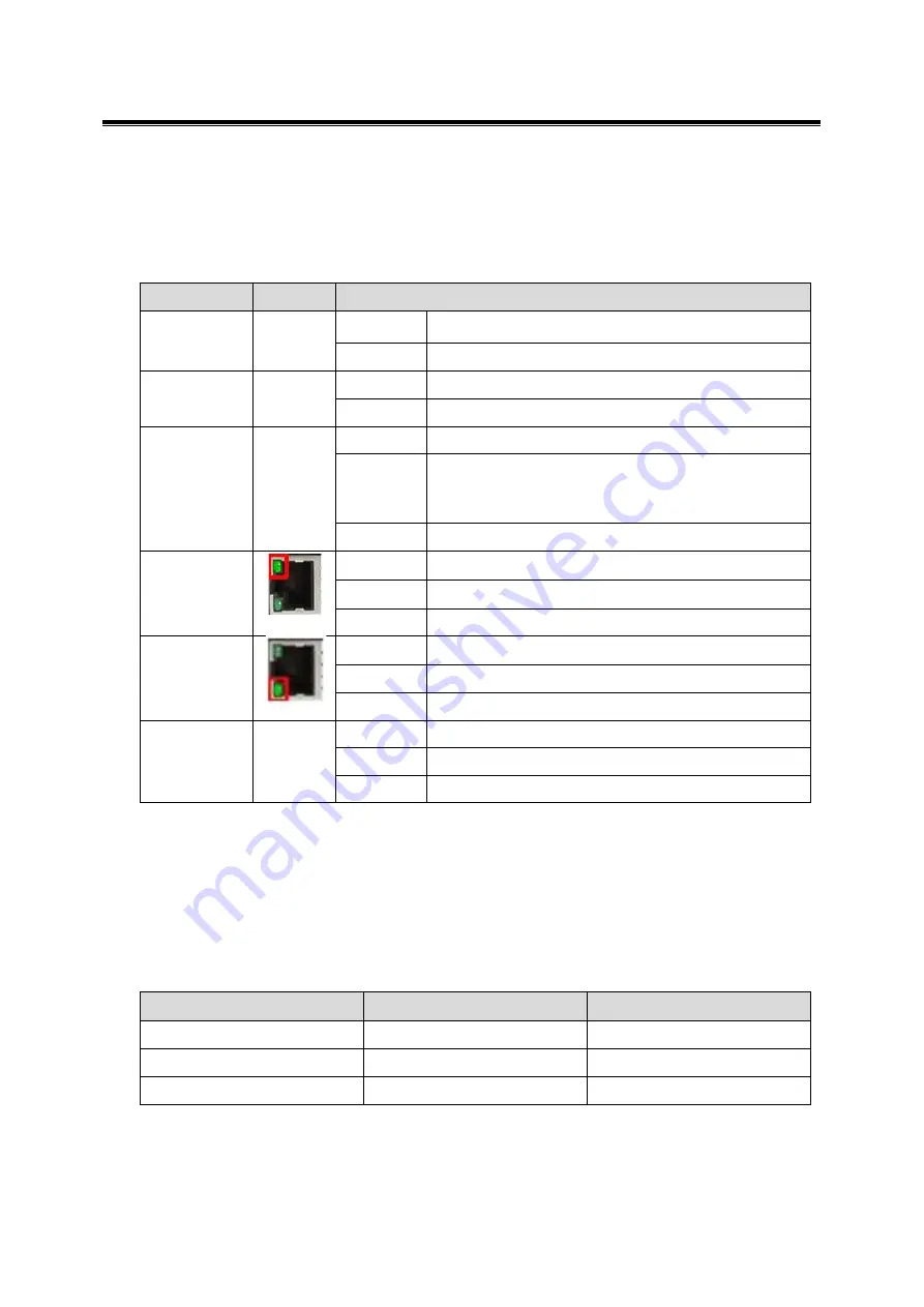
2.4 LED Indicators
There are LED light indicators located on the front panel of the industrial Ethernet media
converter that displays the power and network status. Each LED indicator has a different color
and has its own specific meaning, see below in
Table 2.1
.
LED
Color
Description
Power
Green
On
Power input 1 or 2 is active
Off
Power input 1 and 2 are inactive
AT PoE
Green
On
IEEE 802.3af/at connection
Off
No powered-device attached or power supplying fails
BT PoE
Blue
On
IEEE 802.3bt connection
Flashing
(1 time/s)
1. PoE over current or cable short
2. Invalid connection check signature or connection-
check error is detected
Off
No powered-device attached or power supplying fails
RJ45 Port
(Upper LED)
Green
On
Linked to network at 1000Mbps
Flashing
Networking is active
Off
Not connected to network
RJ45 Port
(Lower LED)
Green
On
Linked to network at 10/100Mbps
Flashing
Networking is active
Off
Not connected to network
SFP Port
Link/Act
Green
On
Connected to network, 100/1000Mbps
Flashing
Networking is active
Off
Not connected to network
2.5 DIP-Switch Setting
There are 3
‐set
s of
DIP‐switch
es on the front panel that are responsible for the settings
of PRRT (PD Remote Reset Technology) function, LFP (Link Fault Pass) function, and SFP
transmission rate (see below in Table 2.2).
DIP-Switch Number
ON
OFF
1
PRRT Enabled
PRRT Disabled
2
LFP Enabled
LFP Disabled
3
SFP 100Fx
SFP 1000Fx
Table 2.1
LED Indicators
Table 2.2
Note: After any DIP switch changes have been made, it is required to power cycle
the unit for the changes to take effect.


