Chapter 4 Operations for Each Function
4-210
4.14.8 Details of clipping processing
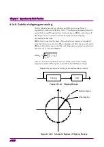
During clipping processing, clipping and filtering are performed
repeatedly, as shown in Figure 4.14.8-1. The clipping processing clips the
peaks that exceed Threshold Level, referencing on RMS
IQ
as the basis (0
dB). Figure 4.14.8-2 shows a schematic diagram of the clipping
processing at this time.
RMS
IQ
that is used as the basis of the clipping processing is calculated
from the following expression. When clipping and filtering are performed,
RMS
IQ
is calculated again, and the next clipping processing is performed
based on the recalculated RMS
IQ
.
(
)
∑
+
=
n
n
n
Q
I
N
2
2
IQ
1
RMS
wherein,
Σ
is the sum of the target waveform patterns (excluding
samples for which RF output is set to Off by the RF Gate setting)
Clipping
Filter
Repeat this procedure according to the set Repetition number
Figure 4.14.8-1 Clipping Process
I
Q
○
Before clipping
●
After clipping
Figure 4.14.8-2 Schematic Diagram of Clipping Process

