


5.4 Generating Waveform Pattern
5-13
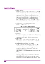
14. Set Burst Setting.
The Burst Setting includes two settings: Frame Length and Gap
Length. The input waveform pattern is divided into frames of the
number of data set by Frame Length, and a gap (burst off period in
which the burst wave is not output) of the number of data set by Gap
Length is inserted between frames (see Figure 5.4-1).
It is not necessary any longer to output the burst off period as a
waveform pattern when using this setting. For example, when
outputting only the first slot in the system where one frame consists
of five slots, the memory length required for the waveform pattern is
reduced to 1/5 of that when the Gap Frame setting is not used.
When an external trigger signal is used, the Frame Length setting is
also used to synchronize the external trigger and the signal output
timing in the Vector Signal Generator option. For details on external
trigger, refer to 3.5.4 “Outputting signal in sync with external
trigger signal” in
MG3700A Vector Signal Generator Operation
Manual (Mainframe)
, or 7.4.1 “Route Input Connectors” in
MG3710A/MG3710E/MG3740A Operation Manual (Mainframe)
. Set
Gap Length to 0 for continuous waves.
Figure 5.4-1 Frame Length and Gap Length Settings
15. Click the Convert button to start data conversion.
The converted data output destination and file name are set, and
waveform pattern generation is started.