


9
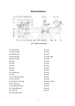
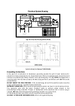
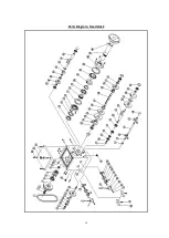
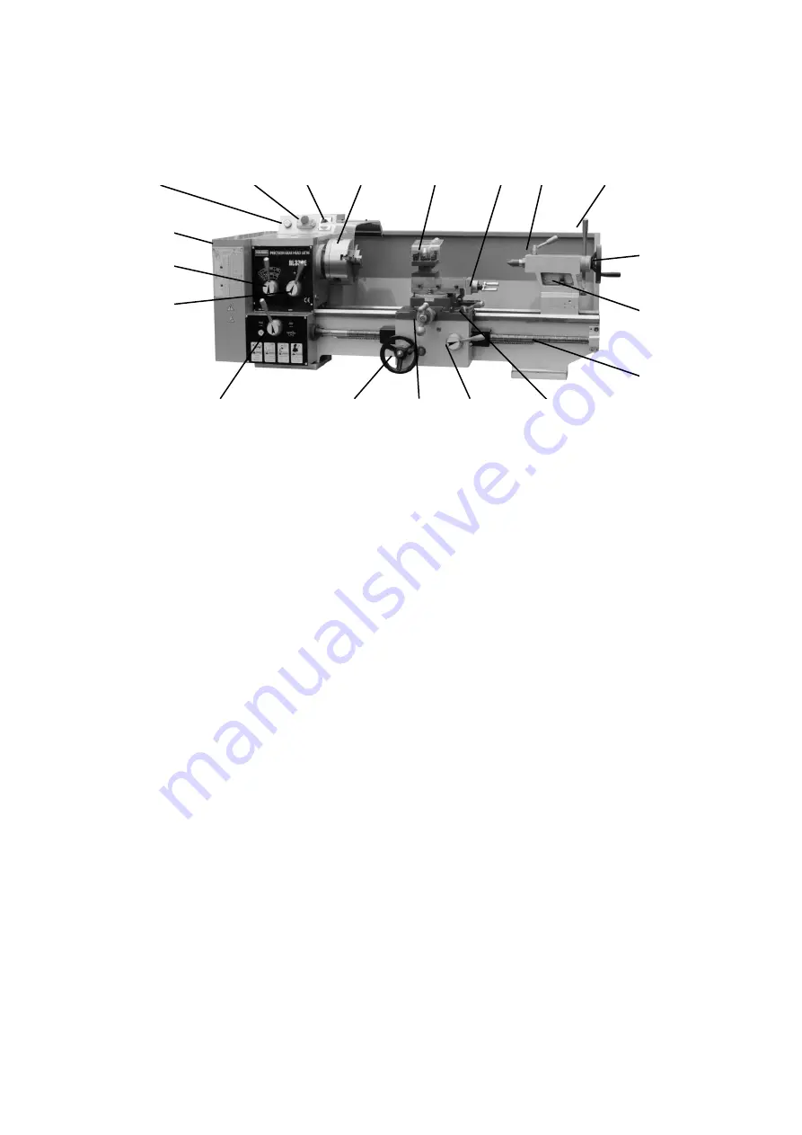
REFER TO THE DIAGRAM BELOW FOR THE BL330E operation controls.
Fig 8. Operation Parts Fig.
1.
Handler of Spindle Speed Change A
2.
Handler of Spindle Speed Change B
3.
Change Gear Box
4.
Power Indictor
5.
Emergency Stop Switch
6.
Forward-Stop-Reverse Switch
7.
Self-centering 3 Jaw Chuck
8.
Handler of 4-way Tool Post
9.
Tool Post Feeding Handler
10.
Handle Lock for tailstock center
11.
Lever to lock Tailstock
12.
Tailstock hand-wheel
13.
Tailstock Offset Screw
14.
Main Lead-screw
15.
Longitudinal-cross feed handle
16.
Handler of Auto-Feed (Half Nut)
17.
Carriage Cross Feed hand wheel
18.
Apron feed hand-wheel
19 Handle of forward/reverse for lead screw
4 5 6 7 8 9 10 11
3
2
1
19 18 17 16 15
12
13
14
Summary of Contents for BL330E
Page 1: ......
Page 10: ...10 ...
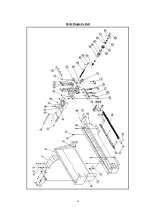
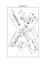
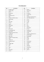
Page 14: ...14 Parts Diagram Headstock ...
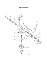
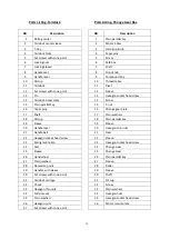
Page 16: ...16 Parts Diagram Trestle ...
Page 18: ...18 Parts Diagram Bed ...
Page 20: ...20 Parts Diagram Apron ...
Page 22: ...22 Parts Diagram Tailstock ...