


13
Adjustment
After a period time, wear in some of the moving components
may need to be adjusted.
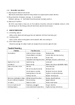
Compound Rest Adjustment
Loosen the two screws (A. Fig. 20), after you have obtained the
angle you want, do not forget to tighten them again.
Fig. 20
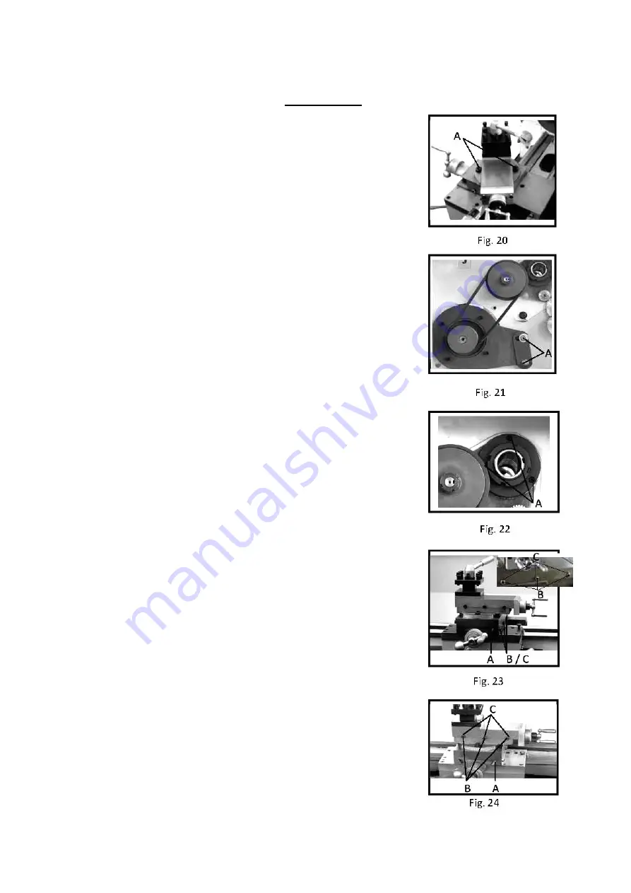
Belt Adjustment
Loosen the two nuts and screws (A. Fig. 21) to remove the plate
of mounting motor and position.
Fig. 21
Main Spindle Bearing Adjustment
The main spindle bearings are adjusted at the factory. If end play
becomes evident after considerable use, the bearings may be
adjusted. Loosen two hex socket cap screws (A, Fig. 22) in the
slotted nut on the back of spindle. Tighten slotted nut until all end
play is taken up. The spindle should still revolve freely.
Tighten two hex socket cap screws.
Caution: excessive tightening or preloading will damage the bearings
Fig. 22
Cross Slide Adjustment
The cross slide is fitted with a gib strip (A, Fig. 23) and can be adjusted
with screw (B, Fig. 23) fitted with lock nuts (C, Fig. 23). Loosen the
lock nuts and tighten the set screws until slide moves freely without
play. Tighten lock nuts to retain adjustment.
Fig. 23
Top Slide Adjustment
The top slide is fitted with a gib strip (A, Fig. 24) and can be adjusted
with screw (B, Fig. 24) fitted with lock nuts (C, Fig. 24). Loosen the
lock nuts and tighten the set screws until slide moves freely without
play. Tighten lock nuts to retain adjustment.
Summary of Contents for BL330E
Page 1: ......
Page 10: ...10 ...
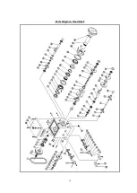
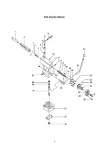
Page 14: ...14 Parts Diagram Headstock ...
Page 16: ...16 Parts Diagram Trestle ...
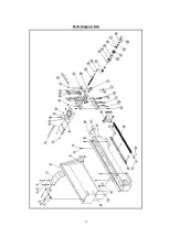
Page 18: ...18 Parts Diagram Bed ...
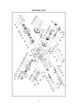
Page 20: ...20 Parts Diagram Apron ...
Page 22: ...22 Parts Diagram Tailstock ...


