background image

17

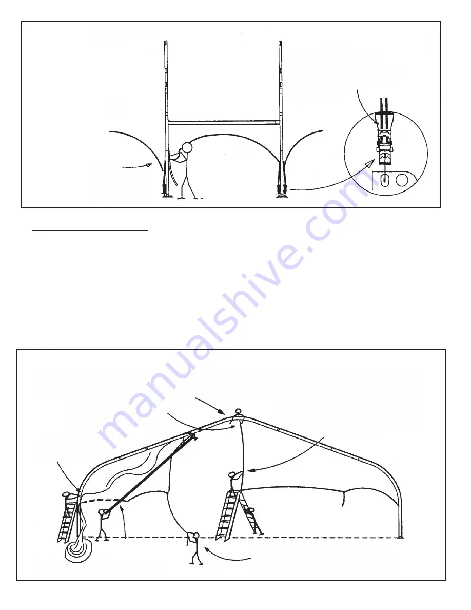
Tensioning of Middle Panels:  (See Above)
1.  Tuck the fabric tails of each panel downward into the beam channel flare until all 
    middle panel kedar rests within the outer beam channel.
2.  Install (2) fabric tensioning winches with hooks into each baseplate, as shown.
3.  Insert the tension webs of each middle panel through the slot in the spindle of each
    fabric winch and pull all surplus webbing through the winch.  
4.  Crank the handle of the winch so that the webbing is wrapped around the spindle.
    Install Gabled End Fabric Panel  (See Top of Page 18)
5.  Coordinate the tensioning of all four corners of each middle panel, so that tensioning 
    is equalized and wrinkles are avoided.  Metal pull rings should be equal distance
    above the baseplate at all four corners of the panel. 

Insert web tail 
through spindle.  
Ratchet handle up 
& down to tension 
fabric

Tuck kedar tail 
downward into 
outer beam channel

Tensioning of Middle Panels

Using a safety line tied off to the frame system, a worker 
lays on last middle panel and engages caribiner to join the 2 
halves of the gabled end and lace down the first 3 or 4 loops.

2 piece end is joined by caribiners at 
top and bottom of lace line.

Feed into Liner 
Channel

Lacing is completed from ladder at 
ground level.  (Minimum 12’ ladder  see 
step #5, next page.  For full lace, use 
14’ ladder or taller.

In a strong breeze, attach safety rope to tail of end 
panel to avoid “wind-whip” that could damage fabric 
or injure workers.

Install Gabled End Fabric Panel (See top of page 18)

Push Purlin tool into metal 
ring of fabric to slide panel 
up and into Liner channel

Summary of Contents for AA AnchorSpan

Page 1: ...re the installation or removal of this product ASPANAA 920 Installation Instructions AA AnchorSpan 30 40 50 60 Wide EC5549 7701 Highway 41 N Evansville IN 47725 Phone 812 867 2421 Fax 812 867 1429 1 8...

Page 2: ......

Page 3: ......

Page 4: ...d End Panel 18 Alternate methods for End Installation Sloped Ends Installing End Uprights 19 Completing End Framing Wing End Eave Bars Baseplate Adapter Bars 20 Tensioning Gabled End Panel and Customi...

Page 5: ...t Assembly 1 per end upright see B on chart AA Wing Eave Brackets 1 wing eave bar see Chart x s with squares AA Beam Joint Caps 2 30 4 40 50 or 6 60 beam AA Bent Arm Pin 1 2 x 7 5 8 1 per baseplate 1...

Page 6: ...e Bar L End Upright Adj doubles as Gin Pole for 30 40 50 End Upright 60 doubles as Gin Pole for 60 Wing Eave Bracket underside of beam at each gabled end Baseplate and fabric tensioning winch Mid Eave...

Page 7: ...E WING EAVE BARS ARE LEFT OR RIGHT AA Wing Eave Bar Assembly 15 AA Wing Eave Bar Assembly 10 Endwall Ground Bar 20 Midwall Ground Bar 15 Wingwall Ground Bar 15 Wingwall Ground Bar 10 End Upright Assem...

Page 8: ...r erecting the beams and 2 readily available 12 step ladders as the only aerial equipment The real heart of the AnchorSpan unit is the SpanLatch purlin system that allows a positive lock at each purli...

Page 9: ...s to avoid tripping especially while carrying components or bundles of fabric 7 Do not drag bundles of fabric on concrete asphalt or ground as this can cause damage to the fabric from abrasion through...

Page 10: ...m your local hardware or lumber stores For Anchor prices see the Installation Labor Tools and Equipment page in the AnchorSpan quotation form or call 1 800 544 4445 for quick pricing by phone Socket W...

Page 11: ...point 1 and another tape at point 2 and pull straight until the appropriate width and diagonal measurements for the span you are installing see above chart intersect on the two tapes at point 3 Revers...

Page 12: ...nd beam plate top view sealing washer sealing washer 8 bolt beam upright bracket bracket threaded for assembly bolt end beam plate substituted for purlin end installed installed installed lock nut Spa...

Page 13: ...ther joint bolt locations will be O Bolt Assemblies The 30 span has only 10 X Bolt Assemblies The rafter pattern shown above is for the 60 span See appendix page X 9 for correct rafter pat tern for 30...

Page 14: ...the appropriate purlin end and let the turnbuckle end of the cable hang to the ground See the Terminology drawing on Page 3 for the color code of each cable location See Page 9 for correct bolt assem...

Page 15: ...o safety ropes trail backward under the beam Attach the remaining two beam harness cables to the eye of the gin pole facing the ground see point B Avoid twisting the cable to the gin pole eye facing t...

Page 16: ...tall the dou ble latch eave purlins in the first bay align the first 2 beams perpendicular to the anchoring sur face and connect the lower ends of all cross cabling in the first bay When the first bay...

Page 17: ...and one latching end After the structure is vertically aligned and cross cabled continue raising beams by the same technique using the purlin hook poles to secure each new beam to the standing beams...

Page 18: ...n fabric pull ropes Workers must coordinate pulling so that both sides of the mid panel move together Pull gently until the panel has rounded the curve of the beam Then pull more vigorously until the...

Page 19: ...pective brackets as shown Tension middle panels after eave bars have been installed WIND SpanLatch Purlins Clip rope to fabric panel Rope to workers for pulling 2 to 4 workers for pull ropes 2 workers...

Page 20: ...should be equal distance above the baseplate at all four corners of the panel Insert web tail through spindle Ratchet handle up down to tension fabric Tuck kedar tail downward into outer beam channel...

Page 21: ...the lace line leaving a slight puffy fullness in the flap as a stress release for the Velcro 6 Tuck the tails of the end panel downward into the channel below the flare The Gabled End will be tensione...

Page 22: ...it easier Consult the Footprint Drawing supplied with your structure for correct positioning and anchor each upright with 2 24 stakes or anchor bolts depending upon the loading requirements of your i...

Page 23: ...el as an Internal Partition Note The Gabled End feeds into the Liner or Inner beam channel It is designed with a grommet line on the inside surface of it s kedar tails The wing eave walls lace to this...

Page 24: ...to liner channel of beam Wall Hooks SUNBURST MIDWALL STYLE CATHEDRAL ENDWALL STYLE STANDARD VINYL WALL STYLE WING WALL LEFT VINYL Typical Ground Bar Standard Loop Grommet Lacing Standard Loop Grommet...

Page 25: ...g Wall Installation The 1 piece wing wall is installed labels to the inside by first sliding the kedar edge down into the flare of the outside channel of the end upright column nearest the beam Next i...

Page 26: ...e for various spans lengths X 5 Guidelines for Disassembly X 6 Weights Measures and suggestions for packing and storage X 7 Template Drawings for the baseplates and the anchor plates for end uprights...

Page 27: ...e end of the eave bar and then the other to avoid drop out 5 On each side of the adapter wall feed the 2 kedar edges simultaneously downward into the AnchorSpan beam channel for midwalls or end uprigh...

Page 28: ...4th loops then attach it to the stationary clip at bottom of the panel 4 Clip the hook that rides on the web tail into the bottom channel of the end eave bar then feed the tail into the web buckle on...

Page 29: ...8 15 3 22 315 57 6 9 6 68 2 11 4 83 4 13 9 96 16 23 330 60 10 71 2 11 9 87 14 5 100 2 16 7 24 345 62 4 10 4 74 2 12 4 90 6 15 1 104 4 17 4 25 360 64 8 10 8 77 2 12 9 94 2 15 7 108 6 18 1 Times Numbers...

Page 30: ...r damaging the beam as the beam is lowered to the ground Lowering of Beams Remove middle eave bars then follow instructions below To release SpanLatch purlins push pointed end of purlin hook into rele...

Page 31: ...sily strapped together in bundles Wingwall Ground Bar 10 10 X x1 x 9 4 0 06 Easily strapped together in bundles Wingwall Ground Bar 15 16 X x1 x 14 4 0 1 Easily strapped together in bundles Adjustable...

Page 32: ...IDE BASE PLATE CENTER SPOTTING HOLE AnchorSpan AA TEMPLATE DRAWING FOR SIDE AND END UPRIGHT BASE PLATES 1 6 1 2 7 8 DIA 7 2 4 4 5 1 2 7 1 2 7 1 2 9 TO INSIDE OF STRUCTURE SIDE LINE OF STRUCTURE INSIDE...

Page 33: ...300 1000 2200 50 AA Temporary 15 2 3100 840 1600 1000 1800 60 AA Temporary 15 2 4100 1020 1700 1400 2100 In order for the AnchorSpan to meet the requirements of its engineering calculations and be cer...

Page 34: ...both ends The 30 ft span uses no rafters The 40 ft span uses only a pair of short rafters to complete the beam arch The 50 ft span uses only a pair of long rafters to complete the beam arch The 60 ft...

Page 35: ...am Stabilize second beam by engaging SpanLatch purlins between first and second beams When second beam is stable divide crew so that half reposition the gin pole for the third beam and half attach dou...

Page 36: ...X 11 NOTES...

Page 37: ...d to do so Recommended Maintenance Tips Fabric components should be cleaned as needed with mild laundry detergent and soft bristled brushes or mops and rinsed and dried thoroughly before being stored...

Page 38: ...VLWH 6WDNLQJ LQIRUPDWLRQ SURYLGHG LQ WKH LQVWDOODWLRQ LQVWUXFWLRQV LV QRW D VXJJHVWLRQ DERXW ZKDW LV QHFHVVDU WR PHHW D VLWH VSHFL F ORDG RU DGGLWLRQDO LPSRUWDQW LQIRUPDWLRQ FRQVXOW 7KH 3URFHGXUDO DQ...

Reviews: