


Control Wiring
ANCA Motion
D-000088 Rev 09
79
7
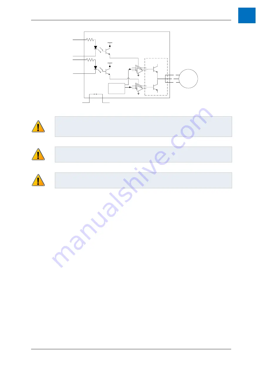
AMD2103 or AMD2109
Controller
3-Phase
V
W
U
Fault Relay
NC during use
Motor
STO Input 1
STO Input 2
Figure 7-17 STO Implementation
Warning:
STO does not remove AC power from the drive itself. If maintenance or repair work is
to be carried out on the machine, the drive should be isolated from all power supplies first. Please
read the User Guide for isolation requirements and techniques. You must also wait for
15 minutes
after power removal for internally stored energy to discharge.
Warning:
It is not recommended to stop the drive using the STO function as this is an uncontrolled
stop. The motor will only coast to a stop and depending on the application this may result in
unacceptable behaviour.
Warning:
When using a three phase permanent magnet synchronous motor and in the case of
multiple gate failure, the motor may unexpectedly rotate up to 180 electrical degrees (180/p
mechanical degrees where p is the number of poles).
7.7.3 STO Considerations
Suitably qualified, trained and authorised personnel must configure and commission STO for use on a
machine.
A hazard analysis must be carried out to evaluate safety risks and to design a suitable safety system in
which STO may be integrated.
This drive must be installed in a suitable location under suitable ambient conditions (see section
.
Acceptance tests must be performed to verify the correct operation of the safety system and STO
function of this drive. The acceptance test procedure (see section
7.7.8 STO Function Commissioning
Test Procedure
) should be carried out after any of the following occur:
o
On initial installation and commissioning of the safety function.
o
After making any changes to the system including wiring, components or settings.
o
Any time a STO Override Plug (
11.4.5 STO Override Plug
) is removed from the X4 interface
for the purpose of returning STO to operation.
o
After any maintenance of the machine or machine safety system.
The STO feature contains no user maintainable components, and will therefore not require any user
maintenance. No opening of the drive for maintenance should be attempted, and any such attempt will
result in the STO feature no longer being considered as providing a safe function. Anti-tamper stickers
are clearly shown on the drive to discourage such maintenance.
Replacement of the fan assembly on
the D2109 is specifically exempt and is the only maintenance allowed on the Drive.
This STO feature is designed for uncontrolled stops (similar to Stop category 0, IEC 60204-1); only
removing torque from the motor. The speed at which the motor and load moves after activation may
depend on many factors.
Summary of Contents for AMD2000 Series
Page 1: ...AMD2000 Series D2xxx Servo Drive User Guide D 000088 Rev 10 ...
Page 131: ...Technical Data ANCA Motion D 000088 Rev 09 119 10 ...
Page 132: ...AMD2000 Series D2xxx Servo Drive User Guide 120 D 000088 Rev 10 ANCA Motion 10 9 1 2 3 Phase ...
Page 133: ...Technical Data ANCA Motion D 000088 Rev 09 121 10 ...
Page 135: ...Technical Data ANCA Motion D 000088 Rev 09 123 10 ...
Page 136: ...AMD2000 Series D2xxx Servo Drive User Guide 124 D 000088 Rev 10 ANCA Motion 10 9 2 2 3 Phase ...
Page 137: ...Technical Data ANCA Motion D 000088 Rev 09 125 10 ...
Page 139: ...Technical Data ANCA Motion D 000088 Rev 09 127 10 ...
Page 140: ...AMD2000 Series D2xxx Servo Drive User Guide 128 D 000088 Rev 10 ANCA Motion ...
Page 141: ...Technical Data ANCA Motion D 000088 Rev 09 129 10 10 9 3 2 3 Phase ...
Page 142: ...AMD2000 Series D2xxx Servo Drive User Guide 130 D 000088 Rev 10 ANCA Motion ...


