


AMD2000 Series D2xxx Servo Drive - User Guide
82
D-000088 Rev 10
ANCA Motion
7.7.5 STO Wiring
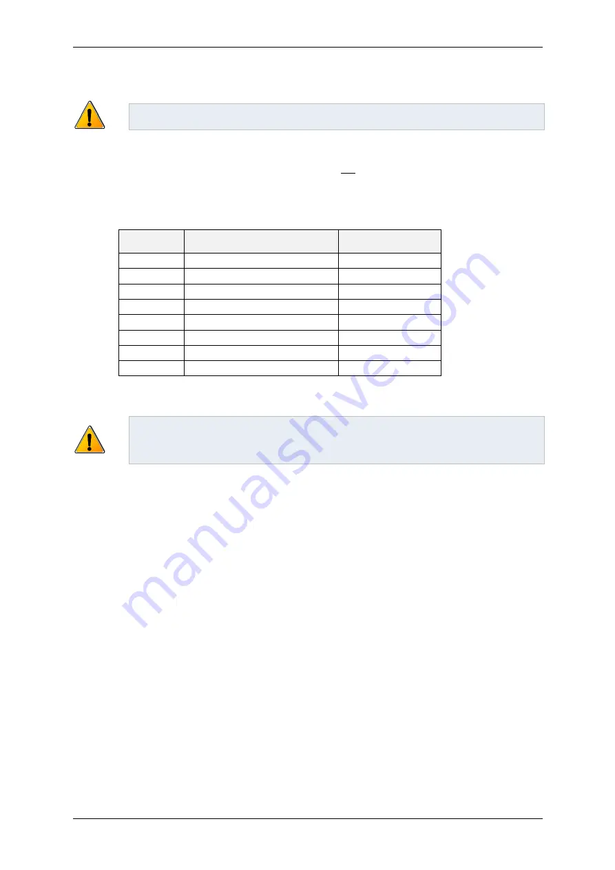
Warning:
Wiring of the AMD2000 for STO must be designed and commissioned by suitably
qualified personnel.
STO uses an isolated dual channel implementation so that the function is fault tolerant, however both channels
need to be asserted or de-asserted within 120ms for the drive to
not
detect a fault. I/O pins and nominal
voltages for each are given in the following table. It is not necessary to use the drive’s internal power supply to
power the STO inputs, but any external power supply must be suitably PELV and must be appreciated for its
impact on the safety function by qualified personnel, such as by approval to IEC 60950.
Name
AMD2000 I/O interface module
Nominal voltage
+STO 1
45
+24 VDC
-STO 1
43
0 VDC
+STO 2
49
+24 VDC
-STO 2
50
0 VDC
SFR-A
5
+24 VDC
SFR-B
6
+24 VDC
+24V
20 & 21
+24 VDC (output)
0V
46 & 47
0 VDC (output)
Table 7-2 - STO connections
Warning:
The STO inputs are electrically isolated from each other, and isolated from the internal
+24V power supply. Cable inputs should be suitably wound, suitably separated, shielded and
grounded, and may not exceed 15 m in length. Avoid tight bending and installations leading to
abrasion in the cable.
If STO is not required for machine safety, then both STO channels can be connected directly to the drive’s own
24V power supply as described in section
7.7.5.5 When STO is not required
, or some other suitable 24V power
supply. Example wiring diagrams are given elsewhere in this document (see
7.7.5.1 Example Wiring Installation
for a Single AMD2000 using STO
and
7.7.5.2 Example Wiring Installation for Multiple AMD2000 using STO
). Any
switching contacts on the STO inputs must operate within 120ms of each other; otherwise a fault will be detected
as described in section
Several common external failure modes result in safe state via the action of the STO function.
In the event that a STO input (I/O 45,43 and/or I/O 49,50) is wired with reverse polarity, the STO circuit
will detect a STO assertion on that channel, and the drive will enter the safe state.
STO input wires that fail to transmit the required threshold voltage (e.g. due to corrosion) will be
detected as STO assertion on that channel, and the drive will enter the safe state.
Similarly, cable disconnections or failures to connect will also result in STO assertion.
If either of the above failure modes occurs on just one channel, then this fault will be registered by the
drive by opening its fault relay.
Some external failure modes are difficult to detect via the actions of the STO function alone (for example, crossed
wiring of inputs), so information regarding the sensed levels of STO inputs, STO reactions and faults can be
examined via ANCA MotionBench software
or the drive’s EtherCAT fieldbus. MotionBench and EtherCAT STO
related signals are described in the
AMD2000 Series Servo Drive
– SoE Configuration Guide.
Summary of Contents for AMD2000 Series
Page 1: ...AMD2000 Series D2xxx Servo Drive User Guide D 000088 Rev 10 ...
Page 131: ...Technical Data ANCA Motion D 000088 Rev 09 119 10 ...
Page 132: ...AMD2000 Series D2xxx Servo Drive User Guide 120 D 000088 Rev 10 ANCA Motion 10 9 1 2 3 Phase ...
Page 133: ...Technical Data ANCA Motion D 000088 Rev 09 121 10 ...
Page 135: ...Technical Data ANCA Motion D 000088 Rev 09 123 10 ...
Page 136: ...AMD2000 Series D2xxx Servo Drive User Guide 124 D 000088 Rev 10 ANCA Motion 10 9 2 2 3 Phase ...
Page 137: ...Technical Data ANCA Motion D 000088 Rev 09 125 10 ...
Page 139: ...Technical Data ANCA Motion D 000088 Rev 09 127 10 ...
Page 140: ...AMD2000 Series D2xxx Servo Drive User Guide 128 D 000088 Rev 10 ANCA Motion ...
Page 141: ...Technical Data ANCA Motion D 000088 Rev 09 129 10 10 9 3 2 3 Phase ...
Page 142: ...AMD2000 Series D2xxx Servo Drive User Guide 130 D 000088 Rev 10 ANCA Motion ...


