background image

Installation and Upgrading

17

NI-2100, NI-3100, NI-4100 Hardware Reference Guide

Installing Into An Equipment Rack



Use the rack-mounting brackets (supplied) for equipment rack installations. 



Remove the mounting brackets for flat surface installations.

Rack Mount Safety Instructions



If installed in a closed or multi-unit rack assembly, the operating ambient temperature of the rack 
environment may be greater than room ambient. Therefore, consideration should be given to 
installing the equipment in an environment compatible with the maximum ambient temperature 
50°C.



Installation of the equipment in a rack should be such that the amount of air flow required for safe 
operation of the equipment is not compromised.



Mounting of the equipment in the rack should be such that a hazardous condition is not achieved 
due to uneven mechanical loading.



Consideration should be given to the connection of the equipment to the supply circuit and the 
effect that overloading of the circuits might have on over current protection and supply wiring. 
Appropriate consideration of equipment nameplate ratings should be used when addressing this 
concern.



Reliable earthing of rack-mounted equipment should be maintained. Particular attention should be 
given to supply connections other than direct connections to the branch circuit (e.g. use of power 
strips).

1.

Discharge the static electricity from your body by touching a grounded object.

2.

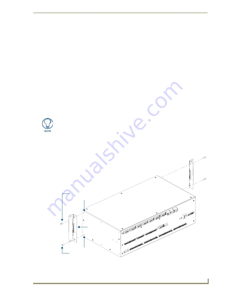
Position and install the mounting brackets, as shown in FIG. 7, using the screws supplied with the unit. 
The mounting brackets can be rotated to accommodate your mounting needs. 

Before completing the install process, it is recommended that you complete any 
firmware upgrade of the NetLinx Control Cards. This upgrade involves physically 
cycling power to the unit and can become cumbersome if the unit is already installed 
into a rack. Refer to the NI Series NetLinx Integrated Controllers WebConsole & 
Programming Guide (available online at www.amx.com) for detailed instructions.

FIG. 7  

Mounting Integrated Controller into an equipment rack

Install screws

Bracket

Rack Mounting Holes

Rack Mounting Holes

Install screws

Summary of Contents for NetLinx Integrated Controller NI-2100

Page 1: ...ardware Reference Guide NetLinx Integrated Controllers NI 2100 3100 4100 NetLinx Integrated Controllers Last Revised 3 01 2012 NI 2100 3100 4100 NetLinx Integrated Controllers Hardware Reference Guide...

Page 2: ...ked on the outside of each box The RMA is valid for a 30 day period After the 30 day period the RMA will be cancelled Any shipments received not consistent with the RMA or after the RMA is cancelled w...

Page 3: ...Accessing The Internal Components On An Integrated Controller 15 Installation of Compact Flash Upgrades 16 Closing and Securing the Outer Housing 16 Installing Into An Equipment Rack 17 Rack Mount Saf...

Page 4: ...t Connections and Wiring 25 ICSNet Port Connections and Wiring 26 ICSHub OUT Port Connections and Wiring 27 Relay Port Connections and Wiring 27 Relay Connections 27 Input Output I O Port Connections...

Page 5: ...ng feedback methods Dynamic Device Discovery makes integration even easier by automatically identifying and communicating with devices which support this beaconing technology Features References withi...

Page 6: ...led The NI 3100 is JITC Compliant the NI 3100 256 is not JITC Compliant Note The NI 3100 can be upgraded to provide 1 ICSHub and 2 ICSNet ports by installing the optional ICSNet daughter card FG2105 1...

Page 7: ...DIP Switch ID Pushbutton ETHERNET 10 100 Port AxLink Port 12 VDC PWR Connector Verify you are using the latest NI firmware for the on board Master Verify you are using the latest version of NetLinx S...

Page 8: ...trolled Supports up to 4 independent external relay devices Channel range 1 4 Each relay can switch up to 24 VDC or 28 VAC 1 A 8 pin 3 5 mm mini Phoenix female connector provides relay termination Dig...

Page 9: ...6 pin 3 5 mm mini Phoenix female I O connector 41 5063 8 pin 3 5 mm mini Phoenix female Relay connector 41 5083 Installation Kit KA2105 01 8 pin Relay Common Strip 4 rack mount screws 4 washers 2 CC N...

Page 10: ...STATUS LED INPUT LED OUTPUT LED RS 232 422 485 Status LEDs RELAY Status LEDs IR SERIAL Status LEDs I O Status LEDs front rear RS 232 422 485 Ports 1 7 ICSNet ICSHub Ports provided by optional ICSNet d...

Page 11: ...nnels 1 8 are transmitting control data on Ports 9 16 LED indictor for each IR port remains lit for the length of time that IR Serial data is being generated I O yellow Lights when the rear I O channe...

Page 12: ...e Ethernet cables are connected and terminated correctly and blinks when receiving Ethernet data packets AxLink Port 4 pin 3 5 mm mini Phoenix male connector that provides data and power to external c...

Page 13: ...n The NI 4100 provides higher performance with a faster processor up to 256 MB of onboard RAM and Duet compatibility The NI 4100 s on board Master also provides the ability to update installed control...

Page 14: ...y red Light to indicate the relay channels 1 8 are active closed These LEDs reflect the state of the relay on Port 8 IR Serial red Light to indicate the IR Serial channels 1 8 are transmitting control...

Page 15: ...D lights On when the Ethernet cables are connected and terminated correctly and blinks when receiving Ethernet data packets AxLink Port 4 pin 3 5 mm mini Phoenix male connector that provides data and...

Page 16: ...information on using the on board Web Console as well as NetLinx send commands and terminal communications to configure the NI Controllers refer to the NetLinx Integrated Controller WebConsole Program...

Page 17: ...re it to the chassis by inserting the three screws by turning them in a clockwise direction and securing the front plate to the Integrated Controller 6 Install all rear connectors and apply power Sett...

Page 18: ...e Device number System and Port are omitted the NetLinx Compiler assumes it has a Port number of 1 and a System number of 0 However you should convert all existing device declarations using the D P S...

Page 19: ...n a counter clockwise rotation The NI 2100 and NI 3100 have six screws on top and three on each side The NI 4100 has six screws on top and four on each side 3 Carefully pull up and remove the housing...

Page 20: ...de card into the connector opening with the arrow facing towards the pins then push it in firmly until the contact pins are completely inside the flash card and securely attached to the connector FIG...

Page 21: ...the circuits might have on over current protection and supply wiring Appropriate consideration of equipment nameplate ratings should be used when addressing this concern Reliable earthing of rack moun...

Page 22: ...pply before plugging in the 2 pin power connector 5 Slide the unit into the rack until the attachment holes along both sides align to their corresponding locations on the mounting brackets as shown in...

Page 23: ...ntroller This mode should only be used when you suspect the resident NetLinx program is causing inadvertent communication and or control problems If necessary place the on board Master in PRD mode and...

Page 24: ...iring The Integrated Controllers are equipped with a Program port located on the front of the unit Use an RS232 programming cable to establish a connection between this Program port to your PC s COM p...

Page 25: ...DHCP server Fast Blink Off Off Downloading Boot firmware Downloading Boot firmware to the Master s on board flash memory Do not cycle power during this process Fast Blink Fast Blink Fast Blink No pro...

Page 26: ...the rear 2 pin 3 5 mm mini Phoenix PWR connector Use the power requirements referenced in the product s Specifications table to determine the power draw The incoming PWR and GND cable from the power s...

Page 27: ...FIG 9 1 Insert the PWR and GND wires on the terminal end of the 2 pin 3 5 mm mini Phoenix cable Match the wiring locations of the on both the power supply and the terminal connector 2 Tighten the cla...

Page 28: ...e on the AXlink PWR connector when using a separate 12 VDC power supply Do not connect the PWR wire to the AXlink connector s PWR opening FIG 11 4 pin mini Phoenix connector wiring diagram using exter...

Page 29: ...licable to the rear RS 232 422 485 Device Port connectors on the NI 2100 Ports 1 3 NI 4100 NI 3100 Ports 1 7 FIG 12 RS 232 422 485 DB9 male connector pinouts for the rear Device Ports RS 232 422 485 D...

Page 30: ...8 B Pin Wire Color Polarity Function 1 Orange White Transmit 2 Orange Transmit 3 Green White Mic 4 Blue Ground 5 White Blue 12 VDC 6 Green Mic 7 White Brown Receive 8 Brown Receive TIA 568B 1 2 3 4 5...

Page 31: ...I 3100 units 4 on the NI 2100 to the Relay connectors on the Integrated Controller Connectors labeled A are for common B are for output Each relay is isolated and normally open A metal commoning strip...

Page 32: ...The PWR pin provides 12 VDC 200 mA and is designed as a power output for the PCS Power Current Sensors VSS2 Video Sync Sensors or equivalent The GND connector is a common ground and is shared by all...

Page 33: ...ns are listed in the following table FIG 15 IR SERIAL male IR Serial Connector Wiring Specifications per Port of IR connections NI 2100 Port Signal Function 1 5 GND Signal 1 Signal GND IR Serial data...

Page 34: ...8 7 5 4 3 2 1 14 NI x100 Controllers feature an Auto MDI MDI X LAN port This provides the option of using either a standard straight through or a crossover LAN cable to communicate with a PC both cab...

Page 35: ...of HTTP v1 1 This port is used for unsecure HTTP Internet communication between the web browser s UI and the target Master 80 TCP HTTPS SSL This port is used by a web browser to securely communicate...

Page 36: ...Connections and Wiring 32 NI 2100 NI 3100 NI 4100 Hardware Reference Guide...

Page 37: ...Connections and Wiring 33 NI 2100 NI 3100 NI 4100 Hardware Reference Guide...

Page 38: ...egistered trademarks of AMX AMX reserves the right to alter specifications without notice at any time It s Your World Take Control 3000 RESEARCH DRIVE RICHARDSON TX 75082 USA 800 222 0193 469 624 8000...

Reviews: