background image

14

Installation

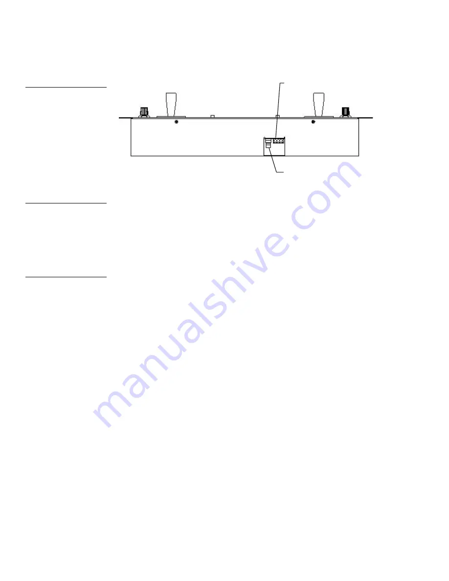
AXP-CCV/AXM-CCV Color Video Camera Centers

AXlink (female) connector site

BNC (female) video connector

Preparing captive wires

You will need a wire stripper, soldering iron, and flat-blade screwdriver to prepare
and connect the captive wires.

1. 

Strip 0.25 inch of wire insulation off all wires and apply a light coat of solder to
the ends using a soldering iron.

2. 

Insert each wire into the appropriate opening on the connector according to the
wiring diagrams and connector types described in this section.

3. 

Turn the flat-blade screws clockwise to secure the wire in the connector.

Wiring guidelines

The AXP-CCV and AXM-CCV require 12 VDC power to operate properly. The
AXCESS Control System supplies power via the AXlink cable or external auxiliary
12 VDC power supply. The maximum wiring distance between the control system
and camera centers is determined by power consumption, supplied voltage, and the
wire gauge used for the cable. Figure 15 lists wire sizes and the maximum lengths
allowable between the camera centers and control system. The maximum wiring
lengths for using AXlink power are based on a minimum of 13.5 VDC available at
the control system’s power supply.

Figure 14

AXM-CCV rear panel AXlink

connector (top view)

Caution

Do not connect power to the

camera center until the wiring

is complete. If you are using a

12 VDC power supply, apply

power to the panel only after

installation is complete.

Caution

Do not over-torque the screw.

Doing so can bend the seating

pin and damage the connector.

Summary of Contents for AXM-CCV

Page 1: ... DPHUD RQWURO 6 VWHPV 30 92 00 9 RORU 9LGHR DPHUD HQWHUV QVWUXFWLRQ 0DQXDO ...

Page 2: ...r made by you for a third party This limitation of liability applies whether damages are sought or a claim is made under this warranty or as a tort claim including negligence and strict product liability a contract claim or any other claim This limitation of liability cannot be waived or amended by any person This limitation of liability will be effective even if AMX or an authorized representativ...

Page 3: ...he AXP CCV 11 Installing the AXM CCV 12 Wiring the AXP CCV and AXM CCV 13 Preparing captive wires 14 Wiring guidelines 14 Using AXP CCV mini XLR connector for AXlink data and power 15 Using AXP CCV mini XLR connector for AXlink and an external 12 VDC power supply 15 Using AXM CCV AXlink connector for data and power 16 Using AXM CCV AXlink connector for data and an external 12 VDC power supply 17 U...

Page 4: ...ii Table of Contents AXP CCV AXM CCV Color Video Camera Centers Mini Color Touch Panel Pages 22 Specifications 27 Overview 27 Technical Support 29 Overview 29 ...

Page 5: ...l to give you graphic touch control and on screen video monitoring with video input for NTSC PAL The touch panel s icons and pushbuttons allow you to select up to 6 cameras with up to 24 presets per camera Optional software provides 18 cameras and 8 preset controls AXlink supports up to 255 devices networked on a wire running up to 3 000 feet from the control system In addition AMX solutions are a...

Page 6: ...e matrix LCD screen Two proportional x y joysticks Two single turn potentiometers POTS 22 programmable pushbuttons equipped with LED for feedback Engraved overlay with pushbutton functions and groupings Compatibility with all AXCESS Control Systems Tabletop mounting AXP CCV or rack mounting AXM CCV For information about creating Touch Panel pages refer to the Color Active Matrix Mini LCD Touch Pan...

Page 7: ...Camera and controller AXlink cable 6 3 amp 12 VDC Power supply Stealth 1 AXB F117 AXlink cable Mini XLR connector BNC video cable What s in this Manual This manual contains the following sections Pre Installation Settings Shows how to set the AXlink device numbers in the AXP CCV and AXM CCV Installation Describes the installation and wiring of the AXP CCV and AXM CCV Figure 3 Sample AXP CCV system...

Page 8: ...ons Technical Support Lists the telephone numbers to call for AMX technical support What s New All new information features and operations added since the previous release of this manual are identified with vertical margin bars Revised the information in the Setting the Touch Panel device number section Added information and drawings to the Wiring the AXP CCV and AXM CCV and Specifications section...

Page 9: ... 1 255 To set the AXP CCV and AXM CCV AXlink device numbers 1 Remove the Phillips head screws from the rear panel 2 Gently rotate the rear panel backward until you can lay it down flat exposing the AXP AI8 Locate the AXlink device DIP switch on the AXP AI8 circuit card Figure 4 AXlink device DIP switch Note You must use unique AXlink device numbers for the AXP AI8 and MCV to be re cognized by the ...

Page 10: ...device number The device number identifies the Mini Touch Panel within the AXCESS Control System Devices connected to the control system must be assigned unique AXlink device numbers Do not use duplicate device numbers to avoid communication problems between the Mini Touch Panel and control system To set the device number 1 Ensure that a mini XLR cable for the AXP CCV or an AXlink cable for the AX...

Page 11: ...Video Camera Centers Pre Installation 7 2 Press the SETUP button and the ADJUST ATTRIBUTES page Figure 7 appears To access the CCV s setup information press PROTECTED SETUP Figure 6 MAIN page Figure 7 ADJUST ATTRIBUTES page ...

Page 12: ...ssing PROTECTED SETUP a setup screen Figure 8 appears 4 Press SET DEVICE to open the device number keypad of the CCV Figure 9 and enter a unique AXlink device number the range is 1 through 255 CLEAR Clears the keypad number Figure 8 Setup screen Figure 9 Device number keypad ...

Page 13: ...with positions 1 6 OFF up to enable joystick and speed control operation Verify that the DIP switch settings on the AXP CCV and AXM CCV match the settings shown in Figure 10 Refer to Setting the AXlink Device Numbers instructions to access the AXP AI8 board I O DIP switch 20 pin Berg header ribbon cable connector 1 2 3 4 5 6 7 8 ON Figure 10 AXP AI8 circuit card s I O DIP switch location Note For ...

Page 14: ...10 Pre Installation AXP CCV AXM CCV Color Video Camera Centers ...

Page 15: ...CCV Camera Centers Since the AXP CCV is a table top configuration Figure 11 it can be mounted on any flat surface whereas the AXM CCV can be mounted within most racks Installing the AXP CCV Front view and dimensions 15 50 393 70 mm Side view and dimensions 7 25 184 15 mm Figure 11 AXP CCV Color Video Camera Center table top front side view and dimensions ...

Page 16: ... from the rear of the AXB EM232 to the rear of the AXP CCV Figure 17 shows another wiring option that has an auxiliary power supply wired directly into the mini XLR cable 4 Connect a BNC video cable from the rear video connector to the video source Installing the AXM CCV You can mount the AXM CCV into most types of electronic equipment racks Figure 12 shows the front view of the AXM CCV 5 22 132 6...

Page 17: ... 10 32 screws 5 Then start the bottom left and top right screws 6 Then tighten all the screws Wiring the AXP CCV and AXM CCV The AXP CCV and AXM CCV communicate with the AXCESS Control System via AXlink The AXP CCV contains a mini XLR female connector on the rear panel for AXlink communication and a BNC female video connection for video input as shown in Figure 13 Mini XLR female connector BNC fem...

Page 18: ...o operate properly The AXCESS Control System supplies power via the AXlink cable or external auxiliary 12 VDC power supply The maximum wiring distance between the control system and camera centers is determined by power consumption supplied voltage and the wire gauge used for the cable Figure 15 lists wire sizes and the maximum lengths allowable between the camera centers and control system The ma...

Page 19: ...for AXlink data and power Connect the control system s AXlink connector to the mini XLR connector male on the rear panel of the AXP CCV for data and 12 VDC power as shown in Figure 16 1 2 3 4 Control system GND 2 1 PWR AXM AXP 3 4 1 GND 3 AXP 2 AXM 4 PWR 4 pin mini XLR connector external view Using AXP CCV mini XLR connector for AXlink and an external 12 VDC power supply Connect the control system...

Page 20: ...t the control system s AXlink connector to the AXlink connector male on the rear panel of the AXM CCV for data and 12 VDC power as shown in Figure 18 PWR AXM AXP GND AXlink connector Control system PWR AXM AXP GND Figure 17 Mini XLR connector to external 12 VDC power supply and control system wiring diagram Caution If you are using power from AXlink disconnect the wiring from the control system be...

Page 21: ...ts described in Figure 15 Make sure to connect only the GND wire on the AXlink connector when using an external 12 VDC power supply Do not connect the PWR wire to the AXlink connector s PWR terminal Using a BNC video cable to provide video input Connect the control system s video connector at the rear panel of the AXM CCV and AXP CCV to the video source as shown in Figure 20 Video Source Front cab...

Page 22: ...18 Installation AXP CCV AXM CCV Color Video Camera Centers ...

Page 23: ...S AXP CCV at 129 CPI for AXP CCS at 130 CPI for AXM CCS at 131 and CPI for AXP CCV at 128 If multiple panels are needed this will require custom code The AXP CCV is mapped channel by channel as is the AXP CCS The CCV has additional buttons pages for remote diagnostics local diagnostics and the rest of the setup The MODE button acts as a multiplier of both the number of cameras and the number of pr...

Page 24: ...all defined by the DIP switch package on the front of the unit The Stealth differs from the AXB CAM in that the hidden setup is crucial for lens type see Figure 26 If the lens type is wrong typically it will operate but it will not go to a preset Channel Assignments Channels correspond to the actual control functions A B C 1 2 3 4 5 6 10 11 12 22 23 24 18 19 20 CHANNEL CHANNEL Figure 22 lists the ...

Page 25: ...de A 11 Mode B 12 Mode C 05 Shot 1 06 Shot 2 07 Shot 3 08 Shot 4 01 Shot 5 02 Shot 6 03 Shot 7 04 Shot 8 21 Store 09 Recall Levels Levels are the values that are related to the analog input or output on the AXP AI8 device in the AXP CCV and AXM CCV The program recognizes the movement of the controls through x y coordinates Figure 23 lists the levels Figure 22 AXP CCV channel assignments Note Refer...

Page 26: ...a whose video feed is being seen If the active camera text is not present the device is not being recognized by the CCV The video feed black in the above example displays a preview of the signal from the camera The above example shows you the eight presets and respective channel assignments available with each MODE Figure 23 Levels Note You can open this file using TP 1 2 or greater Figure 24 AXP ...

Page 27: ...gramming 23 Figure 25 AXP CCV and AXM CCV Camera Iris screen Note This screen allows you to control the aperture of the iris Figure 26 AXP CCV and AXM CCV Camera A Setup Note This screen allows you to adjust the camera s functions This is a one time setup ...

Page 28: ...mera listed at the top of the screen The calibrate joystick allows you to manually calibrate the joystick Figure 27 AXP CCV and AXM CCV Camera B Setup Note Initially the program waits 5 seconds then reads all the levels Figure 23 of the AI8 and begins recalibrating Figure 28 AXP CCV and AXM CCV First Help About box ...

Page 29: ...AXP CCV AXM CCV Color Video Camera Centers AXCESS Programming 25 Figure 29 AXP CCV and AXM CCV Second Help About box ...

Page 30: ...26 AXCESS Programming AXP CCV AXM CCV Color Video Camera Centers ...

Page 31: ...sts its specifications AXP CCV specifications Dimensions HWD 4 80 including joysticks x 15 50 x 7 25 121 00 mm x 393 70 mm x 184 15 mm Weight 4 30 lb 1 90 kg Enclosure Wood with matte black finish Power Consumption 12 VDC 825 mA Connectors 4 pin mini XLR female connector AXlink BNC female Video In connector Figure 30 AXP CCV Camera Center table top configuration Figure 31 AXP CCV specifications ...

Page 32: ... x 4 75 including joysticks 133 35 mm x 482 60 mm x 120 65 mm Weight 3 80 lb 1 41 kg Enclosure Metal with matte black finish and rack mounts Power Consumption 12 VDC 825 mA Connectors 4 pin connector AXlink BNC female Video In connector Figure 32 AXM CCV Camera Center rack mount Figure 33 AXM CCV specifications ...

Page 33: ...am from a new copy of your master disk If you still have a service problem refer to the chart Figure 34 and the map in Figure 35 to determine your team then call your AMX Support Team for technical assistance Sales and Support Team Telephone Numbers Team Telephone Number East 800 75 AMX 75 Central 800 85 AMX 85 West 800 55 AMX 55 Special Projects 800 45 AMX 45 International 1 972 907 6247 Synergy ...

Page 34: ...rademarks of AMX Corporation All other trademarks contained in this document are the properties of their respective owners AMX reserves the right to alter specifications without notice at any time 11995 Forestgate Drive Dallas Texas USA 75243 972 644 3048 800 222 0193 Fax 972 907 2053 www amx com ...

Reviews: