6
AM-TC10626LA
3.
Installation and adjusting
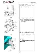
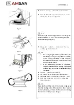
Fig3
Fig4
3.1.
Unpacking
⚫
Unpack according to the instructions on the package.
Remove the packing materials and inspect the machine for
possible damage or loss of accessories during transportation.
In case of doubt do not use the machine and refer to
professionally qualified personnel and/or to the seller.
⚫
Keep the packing materials out of the reach of children.
Handle appropriately if the packing material is likely to
cause pollution.
⚫
Remove the cabinet, column, swing arm, and accessory box
fitted on the bottom plate and keep them in a safe place.
NOTE
:
A special anti-rust oil applied on the delicate parts
may attract dust. Clean it when necessary
.
3.2.
Location
The place to install the machine should be by safety regulations
:
⚫
The machine should be installed in a place close to the main
power source and compressed air system.
⚫
Install the machine on the smooth concrete ground or other
ground with hard flooring. 4 sets of anchor bolts can be used
to fasten the machine onto the ground to avoid vibration and
noise.
⚫
Leave enough space for the operation and maintenance of the
machine. The space should be no less than 1M in front and
on the two sides of the machine, 0.5M behind it so that
operation on different parts shall not be hindered.
⚫
If the machine has to be installed outdoors, a protective
shelter should be built.
⚫
Never operate the machine in a place with flammable gas.
NOTE
:
For safety and proper operation, keep the machine at
least 0.5M away from any wall (Fig
4
)
Summary of Contents for AM-TC10626LA
Page 1: ...PLEASE READ THE PRODUCT MANUAL ENTIRELY BEFORE INSTALLING OR OPERATING THE LIFT ...
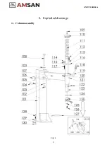
Page 22: ...Fig 34 21 AM TC10626LA 9 1 Column assembly 9 Exploded drawings ...
Page 23: ...Fig 35 22 AM TC10626LA 9 2 Turntable assembly ...
Page 24: ...Fig 36 22 AM TC10626LA 9 3 Gearbox motor assembly ...
Page 25: ...24 AM TC10626LA 9 4 Body assembly Fig 37 ...
Page 26: ...25 AM TC10626LA 9 5 Bead Breaker Cylinder Breaker Arm Assembly Fig 38 ...
Page 27: ...26 AM TC10626LA 9 6 Quick inflating system Optional Fig 39 ...
Page 28: ...27 AM TC10626LA 9 7 Simple left help arm Optional Fig 40 INSTALL ...
Page 41: ...40 AM TC10626LA Appendix 1 Electrical Diagram Fig 40 Fig 41 ...


