36
AM-TC10626LA
Fig.
8
Fig 8-b
●
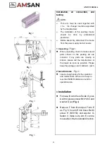
Air connection:
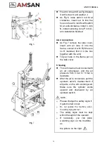
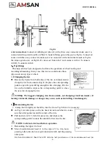
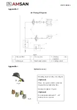
Connect air inflating air tube (A) with a three-way connector (make sure it is
connected with upward mouth) on Filter S; hook inflating gun on the post as Fig8-a. Connect air
source with three-way connector (make sure it is connected with a horizontal mouth as Fig.8-a
the arrow sign shows). As Fig8-b, D comes out from tube C and connects with A, E connects
with B, F connects with G.
3
、
Operation
:
This help arm has been designed to facilitate the operations of wheel locking and
mounting/demounting. In any case, this device would make these
jobs easier on any type of wheel.
1
】
Clamping the tire
⚫
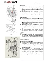
Release the beads from both sides of the tire as manual stated,
clamp the tire from outside (Fig.8). Depress the corresponding
pedal to open the jaws till big enough for rim clamping; Put the
tire on the turntable, depress the corresponding pedal to close
the jaws for clamping the tire.
NOTE
:
We Suggest clamping rim from outside, not clamping rim from inside ( if
locking rim inside, damage or danger may occur, such as tire falling, rim damaged.)
2
】
Demounting the tire
1
)
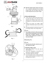
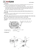
Clamp the rim tightly on the table, lose the tire as Fig.9 when it is necessary.
⚫
As Fig 9, let roller press on the tire bead, do not touch the rim, make
sure the roller points toward the center of the rim
;
⚫
Pull down switch 13, let roller press tire, and depress the
corresponding pedal to rotate the turntable, then lose the tire.
NOTE: Lubricate tire bead before operation.
2
)
Demounting the upper tire bead
⚫
Move mount/demount head A to the edge of t h e rim, leave
pressing roller onto tire bead, pull-down switch D, and the pressing
roller press
tire bead downward. Insert lever B onto
the ball protuberance of the mount/demount head
(as
Fig
9
Summary of Contents for AM-TC10626LA
Page 1: ...PLEASE READ THE PRODUCT MANUAL ENTIRELY BEFORE INSTALLING OR OPERATING THE LIFT ...
Page 22: ...Fig 34 21 AM TC10626LA 9 1 Column assembly 9 Exploded drawings ...
Page 23: ...Fig 35 22 AM TC10626LA 9 2 Turntable assembly ...
Page 24: ...Fig 36 22 AM TC10626LA 9 3 Gearbox motor assembly ...
Page 25: ...24 AM TC10626LA 9 4 Body assembly Fig 37 ...
Page 26: ...25 AM TC10626LA 9 5 Bead Breaker Cylinder Breaker Arm Assembly Fig 38 ...
Page 27: ...26 AM TC10626LA 9 6 Quick inflating system Optional Fig 39 ...
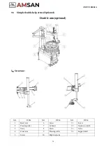
Page 28: ...27 AM TC10626LA 9 7 Simple left help arm Optional Fig 40 INSTALL ...
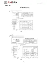
Page 41: ...40 AM TC10626LA Appendix 1 Electrical Diagram Fig 40 Fig 41 ...

