13
AM-TC10626LA
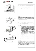
Fig.17
⚫
Before demounting
,
lubricate the tire bead and rim.
⚫
Raise the bead with a special lever and hook it onto
the tongue of the bead
(
as fig.17 18
)
.
NOTE
:
If inner tube, to avoid damage of inner tube, keep the
position of t h e air valve and mounting head at
10cm distance
(
as fig.18
)
Fig.18
Fig.19
Fig.20
⚫
Press pedal A
(
as fig.19
),
turntable turns clockwise,
until the edge of wheel falls off.
NOTE
:
➢
For a very tough and low-profile wheel, the
wheel edge is easy to slip off, to avoid this,
before turning clockwise of the turntable,
may turn anti-clockwise a little to make the
turntable back 1-2mm
.
➢
If the demounting process is prevented,
stop the turntable from turning around, lift
pedal A (fig. 19), let the turntable turn anti-
clockwise
.
⚫
If there is a tube in the tire, remove it.
⚫
Lift wheel, make the bottom edge of wheel as fig.20
)
.
⚫
Press pedal A until the bottom edge of the wheel falls off.
⚫
Push away swing arm
,
take off t h e wheel, and
finish demounting.
NOTE
:
Keep hands and the rest of the human body away
from the moving parts of the machine. Never wear a
necklace, bracelet, or loose clothes when operating
the machine as it may cause danger
Summary of Contents for AM-TC10626LA
Page 1: ...PLEASE READ THE PRODUCT MANUAL ENTIRELY BEFORE INSTALLING OR OPERATING THE LIFT ...
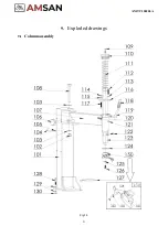
Page 22: ...Fig 34 21 AM TC10626LA 9 1 Column assembly 9 Exploded drawings ...
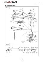
Page 23: ...Fig 35 22 AM TC10626LA 9 2 Turntable assembly ...
Page 24: ...Fig 36 22 AM TC10626LA 9 3 Gearbox motor assembly ...
Page 25: ...24 AM TC10626LA 9 4 Body assembly Fig 37 ...
Page 26: ...25 AM TC10626LA 9 5 Bead Breaker Cylinder Breaker Arm Assembly Fig 38 ...
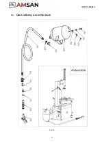
Page 27: ...26 AM TC10626LA 9 6 Quick inflating system Optional Fig 39 ...
Page 28: ...27 AM TC10626LA 9 7 Simple left help arm Optional Fig 40 INSTALL ...
Page 41: ...40 AM TC10626LA Appendix 1 Electrical Diagram Fig 40 Fig 41 ...


