


ISUPS2B004 Rev 1
Page 31 of 70
Ampcontrol Pty Ltd
– ABN 28 000 915 542
ISUPS 300Wh V2 USER MANUAL
ISUPS2B004 R2
– DEC/17
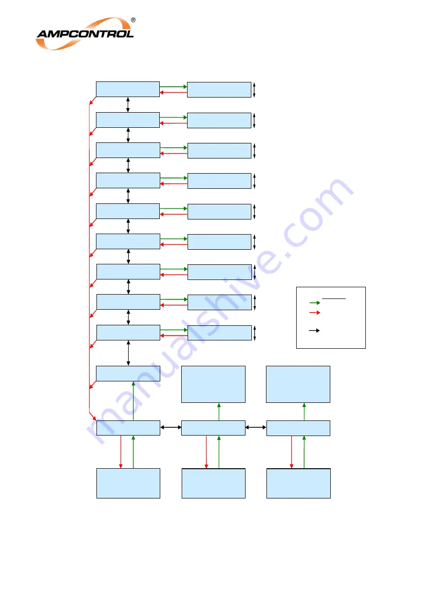
6F1A: Relay 1:
>
OP Over Amps<
OP Over Amps
>
0.0 Amps<
0.0 to 1.5 A
See figure on
preceding page for
initial stages of
structure
See figure on
preceding page for
initial stages of
structure
See figure on
preceding page for
initial stages of
structure
6F1: Relay 1
Configuration
6F2: Relay 2
Configuration
6F3: Relay 3
Configuration
6F1A: Relay 1
>
Off<
6F2: Relay 2
Configuration is
exactly as per
Relay 1 from this
point onwards.
6F3: Relay 3
Configuration is
exactly as per
Relay 1 from this
point onwards.
LEGEND
ENTER
ESC
UP, DOWN,
LEFT, RIGHT
6F1A: Relay 1:
> OP Under Amps<
OP Under Amps
>
0.0 Amps<
0.0 to 1.5 A
6F1A: Relay 1:
> OP Under Volts<
OP Under Volts
>
3.0 Volts<
3.0 to 25 V
6F1A: Relay 1:
> Bat. °C Hi Alarm<
Bat. °C Hi Alarm
>
35°C<
-10°C to +69°C
6F1A: Relay 1:
>
UPS Alarm<
UPS Alarm
>
ACTIVE<
ACTIVE or INACTIVE
6F1A: Relay 1:
>
Mains Status<
Mains Status
>
GOOD<
FAIL or GOOD
6F1A: Relay 1:
> Digital Input<
Digital Input
>
3H+2L+1L<
Refer Section 13.7.8
6F1A: Relay 1:
>
Timer Status<
Timer Status
>
RUNNING<
RUNNING or ALWAYS ON
6F1A: Relay 1:
> Output Status<
Output Status
>
OFF<
OFF or ON
Figure 10.2: Field Configuration Menu
– Final Stages


