Date: 02 Feb 2011
Ampair ® 300 (Mk1, “Pacific”) Wind Turbine Manual
CD 2300
Issue: 1.2
Page 20 of 34
- 20 -
© Ampair, April 2007
stop
switch
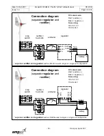
Connection diagram
(stop switch)
BLUE or BLACK = - Negative (YELLOW is preferred colour in the USA)
When mounting the Ampair 300 on its mounting pole or bracket, the cable needs to be fed down through
the mounting. When arranging this cable make sure it cannot chafe at the point where it leaves the
mounting pole. Either lead the cable out of the bottom of the pole in a gentle curve or, drill an exit hole in
the pole large enough to take a rubber grommet to protect the cable from the sharp edges of the hole.
In marine environments cables with tinned multi-strand conductors are recommended to prevent salt air
corrosion which will otherwise cause substantial performance reductions in a short time.
Wiring between the generator (or junction box, connector, etc.) and the battery area should be clipped at
regular intervals to the structure for safety and a neat job.
On boats, to carry power from the Ampair to internal wiring we recommend that a good quality water-tight
connector be fitted
Cable hanging inside masts can be quite heavy. We recommend fitting a strain relief at the top so that the
weight is not carried by the wind turbine. Arrange this strain relief so that if the cable is disconnected from
the wind turbine (so as to remove the wind turbine for maintenance) then the end of the cable can be
secured and not fall down inside the mast.
If there is any
danger of the cable „slatting‟ noisily inside a hollow mast
, then place some closed cell foam
pipe insulation over it as anti-slatting collars.
Maintain a consistent colour scheme throughout the cable runs, and mark line ends with a positive (+) and
negative (-) symbol to minimise risk of errors. At different times and in different countries the colour
schemes used in wiring systems have varied. If reusing old cable runs the only way to be sure is to
carefully trace all the cables and „loop test‟ them
yourself during initial installation,
4.7.2 Fuses and circuit breakers
Fuses or miniature circuit breakers (MCBs) should always be fitted. The simplest possible arrangement
feeds the power from the Ampair directly to the battery via an in-line fuse in the positive line near to the
battery.
WARNING:
Always install a fuse. The fuse should be next to the battery terminal since, in the event
of a fault or damage to the cable, the battery will supply the fault-current.
Do not place the fuse inside the battery compartment itself as, in the event of a build up
of explosive hydrogen/air mixture in the battery compartment, the spark from a blowing
fuse could provide the detonation source.
4.7.3 Parking (stop) switch
We recommend installing a „stop‟ switch which
should be more correctly thought of as a
„parking‟ switch. Just as the parking brake in a
car should not be relied on to stop a car at high
speed, so the parking switch of the Ampair wind
turbine should not be relied on to stop the rotor
disc in high winds. Instead it is best to apply it
before the arrival of very high winds, or if
needing to ensure that the rotor does not move
in low winds (e.g. when approaching the rotor for
maintenance).
The switch should be wired as shown in the
diagram above. If wired in this way the wind
turbine will be stopped with the switch in the
„O
N
‟ or „
1
‟ position, and will run normally with the
switch in the „O
FF
‟ or „
0
‟ position.
IMPORTANT NOTE: The „stop‟ switch is only to be used for stopping
the turbine in order that it can be inspected or to carry out maintenance. In the event of high winds the

